How does the bldc motor rotate, Figure 4-2 names of the respective elements – FUJITSU CAN-Motor Board MB91F267N User Manual
Page 66
AN07-00180-3E
- 66 -
4.2
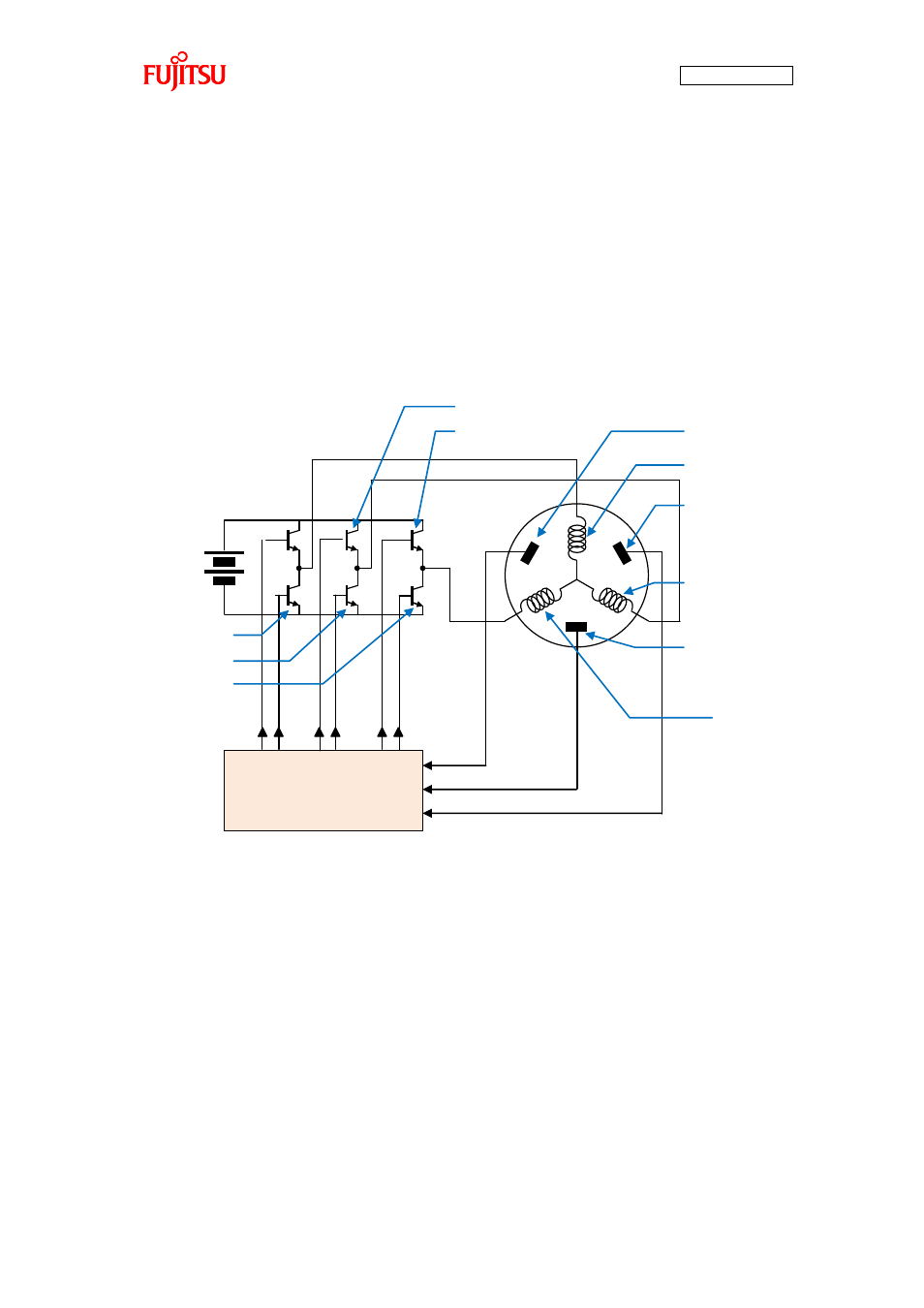
How does the BLDC motor rotate?
The BLDC motor has three phases different by 120°. As shown in “Figure 4-2 Names of the respective
elements”, the phases are called the U-phase, V-phase, and W-phase respectively.
The switches on the driver circuit are respectively called U-High, U-Low, V-High, V-Low, W-High, and
W-Low and connected as outputs from the microcontroller. The hall elements for detection of the rotor
position are respectively called Hall-U, Hall-V, and Hall-W and connected as inputs to the
microcontroller.
Figure 4-2 Names of the respective elements
By turning on/off the switches, the directions of the currents conducted to the motor are controlled. Two
of the three coils are set to positive or negative to generate a magnetic field for motor rotation.
The hall elements are used to detect the position of the rotor by 60° and the detection is represented with
1 or 0. According to their values, the switches are turned on/off. On detection of the hall elements, the
High side of the phase corresponding to it is turned ON, and on no detection, the Low side is turned ON.
“Figure 4-3 120° conduction method time chart” shows their relationship.
This way of driving control is called the 120° conduction method (square-weave control).
Microcontroller
V-phase
U-phase
W-phase
V-High
W-High
W-Low
V-Low
U-Low
Hall-U
Hall-V
Hall-W