Bldc motor rotation control by the microcontroller, Figure 4-4 motor driver circuit – FUJITSU CAN-Motor Board MB91F267N User Manual
Page 68
AN07-00180-3E
- 68 -
4.3
BLDC motor rotation control by the microcontroller
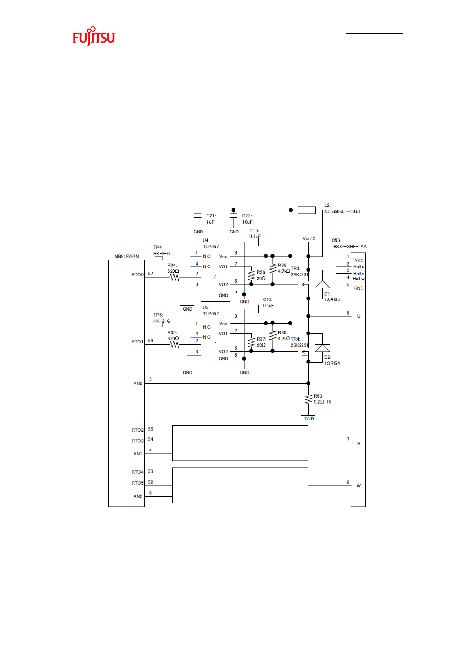
This section describes how the BLDC motor is practically controlled with the 120° conduction method by
the microcontroller.
On the board, as shown in “Figure 4-4 Motor driver circuit”, the microcontroller is connected with the
motor driver circuit. The relationship of the connections with the semiconductor elements described in
“4.2 How does the BLDC motor rotate?” is as shown in “Table 4-1 Microcontroller pin/Motor driver
circuit connections”. By turning RTO0 to 5 on/off according to the positions of the hall elements as
shown in “Figure 4-3 120° conduction method time chart”, the motor can be rotated.
Figure 4-4 Motor driver circuit
Same as RTO0/RTO1
Same as RTO0/RTO1
Anode
Anode
Cathode
Cathode
- XG Series P3NK-4452-01ENZD (614 pages)
- FPCAC14C (1 page)
- MCJ3230SS (161 pages)
- MBA3073NC (138 pages)
- T5140 (76 pages)
- T5140 (102 pages)
- MAM3367MC/MP (152 pages)
- MPC3045AH (185 pages)
- MB2142-02 (23 pages)
- MB15F86UL (6 pages)
- MHS2030AT (40 pages)
- MHW2100BS (296 pages)
- MHK2060AT (227 pages)
- Disk Drives MHK2060AT (227 pages)
- MCM3064SS (170 pages)
- Mainboard D1561 (45 pages)
- MHC2040AT (219 pages)
- D1961 (45 pages)
- DISK DRIVES MHM2100AT (231 pages)
- MHR2010AT (250 pages)
- MHZ2120BJ (320 pages)
- MCE3064AP (175 pages)
- LQFP-64P (16 pages)
- Solaris PCI GigabitEthernet 3.0 (115 pages)
- MAY2036RC (94 pages)
- MAB3091 (142 pages)
- MPE3XXXAT (191 pages)
- MHV2040AH (40 pages)
- MHW2040AC (278 pages)
- ETERNUSmgr P2X0-0202-01EN (64 pages)
- VSS Hardware Provider 2.1 (134 pages)
- MAG3182FC (61 pages)
- MAU3147NC/NP (130 pages)
- MAX3147RC (94 pages)
- MHV2160BT (296 pages)
- MHV2040AT (280 pages)
- MAW3300NC/NP (130 pages)
- DeskPower E623 (50 pages)
- MAG3182LC (133 pages)
- OPTICAL DISK DRIVES MDG3064UB (42 pages)
- MHF2021AT (225 pages)
- MHR2040AT (40 pages)
- Single Drive FTM7926FB (1 page)
- PG-FCS103 (98 pages)
- MAS3735FC (114 pages)