Handling controls of the bldc motor, Figure 4-14 motor controls flowchart – FUJITSU CAN-Motor Board MB91F267N User Manual
Page 78
AN07-00180-3E
- 78 -
4.5
Handling controls of the BLDC motor
You were able to rotate the BLDC motor by using the microcontroller macro. Then, try to control the
rotation speed, brake, and rotation direction now.
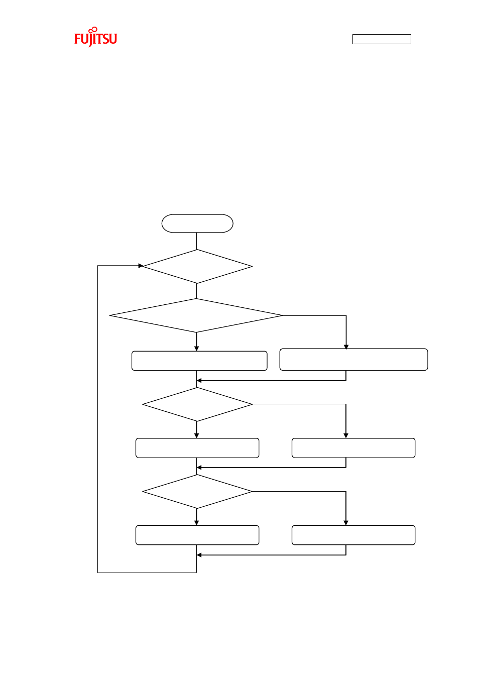
In the sample program, the controls are handled in the infinite loop inside the main function shown in
The rotation speed is determined according to the temperature sensor or input from programmed variables,
and the brake is applied whether SW3 is pressed. The direction of motor rotation is determined according
to the position of SW5. “Figure 4-14 Motor controls flowchart” illustrates how the controls are handled.
Figure 4-14 Motor controls flowchart
Start
Infinite loop
Speed calculation with the temperature sensor
Use of the temperature sensor
Speed calculation with the programmed variables
Press of SW3
Brake released
SW set to the right
Brake applied
Left rotation
Right rotation
false
false
false
true
true
true