Figure 4-5 timer control registers, Table 4-1 microcontroller pin/motor driver, Circuit connections – FUJITSU CAN-Motor Board MB91F267N User Manual
Page 69
AN07-00180-3E
- 69 -
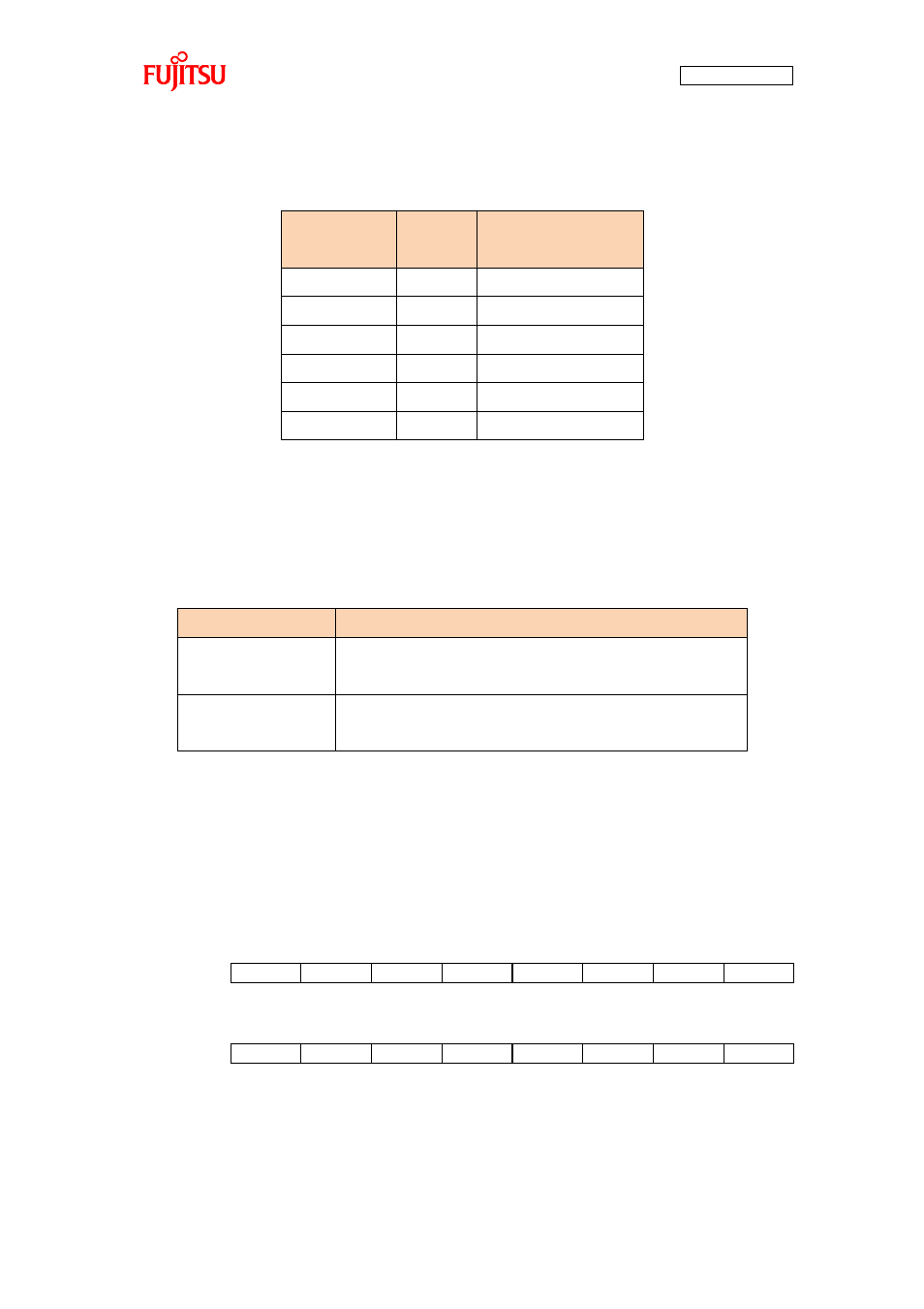
Table 4-1 Microcontroller pin/Motor driver circuit connections
Microcontroller
pin number
Pin name
Name of the semiconductor
element connected
Pin57
RTO0
U-High
Pin56
RTO1
U-Low
Pin55
RTO2
V-High
Pin54
RTO3
V-Low
Pin53
RTO4
W-High
Pin52
RTO5
W-Low
RTO0 to 5 ON/OFF control is practically taken by the macro in the microprocessor mounted on the board.
So, it is necessary to configure registers for functions employed by the macro. “Table 4-2 Functions
employed by the motor driving macro” shows the functions employed.
Table 4-2 Functions employed by the motor driving macro
Function name
Description
16-bit free-run timer
Timer in which an up/down counter is used.
This counter is used to configure the output compare function.
16-bit output compare
Used to make comparisons with the value of the free-run timer,
and the resulting values are used to turn on/off RTO0 to 5.
The registers used for the 16-bit free-run timer are as shown in “Figure 4-5 Timer control registers”. A
description of the registers and their setting values in the sample program are as described in “Table 4-3
Description of the timer control registers and setting values”. For more information of the registers, refer
to the microcontroller hardware manual.
Figure 4-5 Timer control registers
TCCSH0
ECKE
IRQZF
IRQZE
MSI2
MSI1
MSI0
ICLR
ICRE
TCCSL0
BFE
STOP
MODE
SCLR
CLK3
CLK2
CLK1
CLK0
Timer control high-order bits
bit15
bit14
bit13
bit12
bit11
bit10
bit9
bit8
Timer control low-order bits
bit7
bit6
bit5
bit4
bit3
bit2
bit1
bit0