Figure 4-7 operation of the free-run timer – FUJITSU CAN-Motor Board MB91F267N User Manual
Page 73
AN07-00180-3E
- 73 -
Initialize the 16-bit free-run timer and 16-bit output compare functions as shown in “Table 4-3
Description of the timer control registers and setting values”, “Table 4-4 Description of the output
compare registers and setting values”.
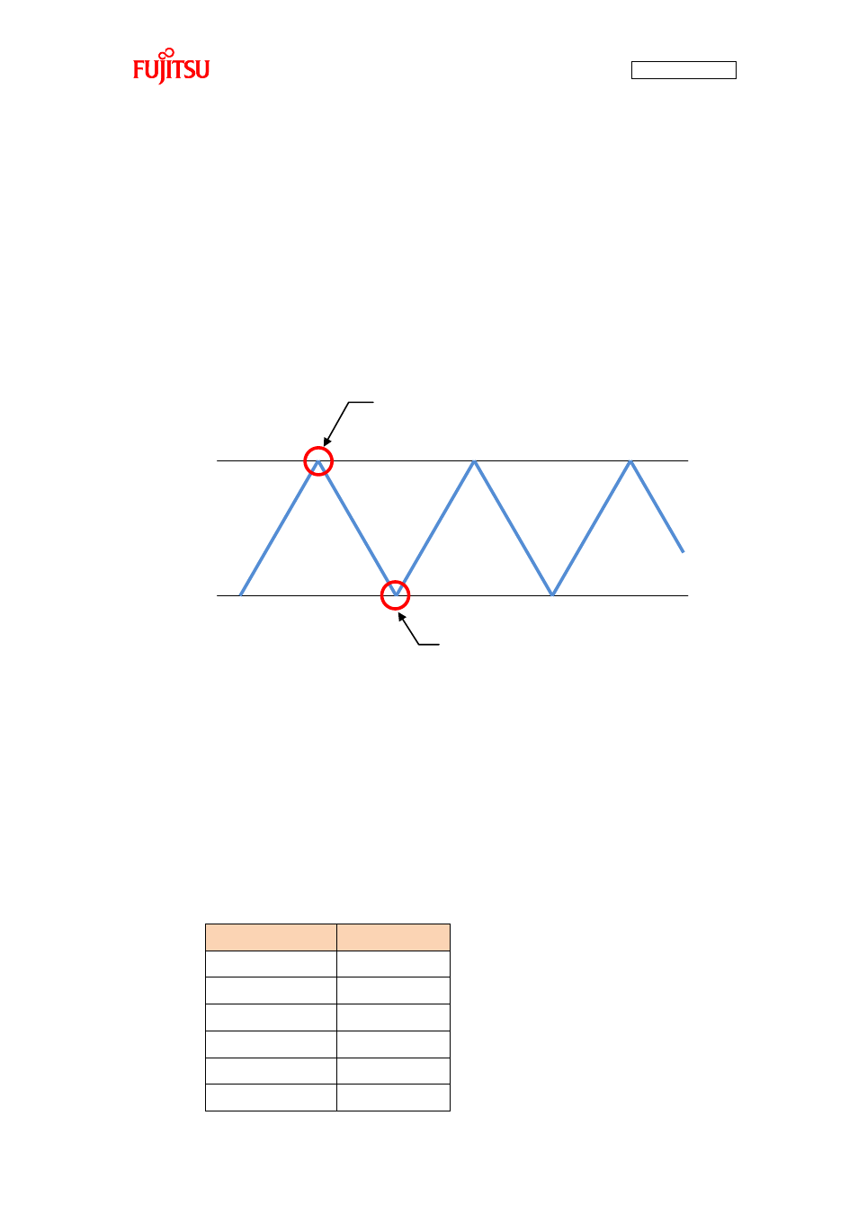
After the initialization, running the 16-bit free-run timer starts a count up using the value configured to
CPCLRB0 as the carrier peak as shown in “Figure 4-7 Operation of the free-run timer”. When the carrier
peak is reached, an interrupt takes place, and according to information about the hall elements on that
occasion, the outputs are switched on/off through comparisons with the output compare values.
After that, a countdown to the carrier bottom (0) is performed. When the count reaches 0, a count up
starts again, and this sequence is repeated.
Figure 4-7 Operation of the free-run timer
The output compare values are respectively configured by OCCPB0-5. According to the values, the
outputs of U-High, U-Low, V-High, V-Low, W-High, and W-Low are turned on/off by the macro. “ Table
4-5 Correspondence between the output compare values and the switchings” shows their association. In
addition to that, “Figure 4-8 U-High output to output comparisons” shows an example of the U-High
output.
Table 4-5 Correspondence between the output compare values and the switchings
Register name
Switching
OCCPB0
U-High
OCCPB1
U-Low
OCCPB2
V-High
OCCPB3
V-Low
OCCPB4
W-High
OCCPB5
W-Low
CPCLRB0 value
0
Carrier peak
(occurrence of an interrupt)
Carrier button
Time→