Figure 4-6 output compare registers – FUJITSU CAN-Motor Board MB91F267N User Manual
Page 71
AN07-00180-3E
- 71 -
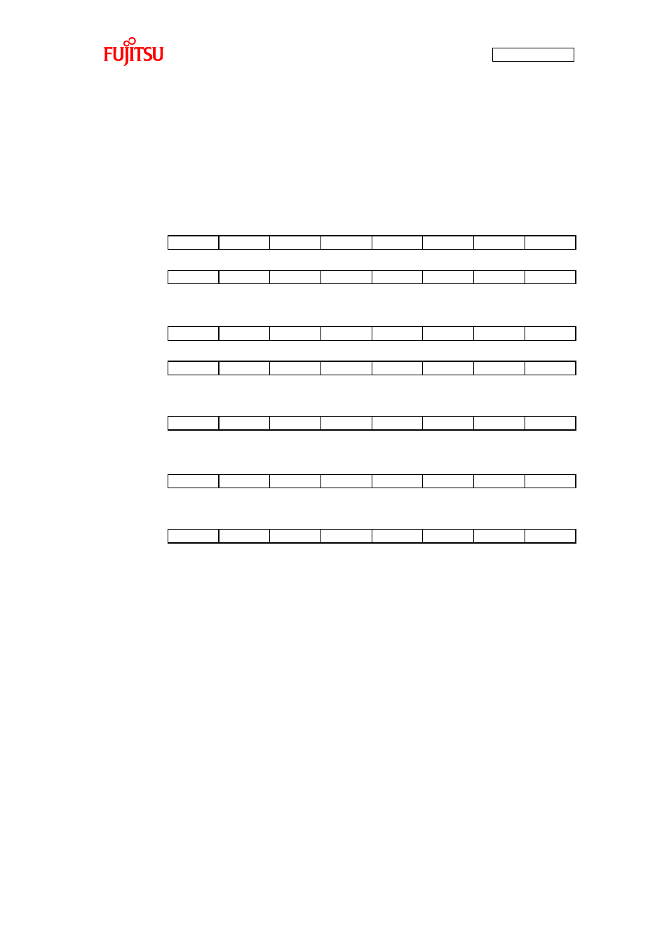
The registers used for the 16-bit output compare function are as shown in “Figure 4-6 Output compare
registers”. A description of the registers and their setting values in the sample program are as described in
“Table 4-4 Description of the output compare registers and setting values”. For more information of the
registers, refer to the microcontroller hardware manual.
Figure 4-6 Output compare registers
CPCLRB0
CL15
CL14
CL13
CL12
CL11
CL10
CL9
CL8
CL7
CL6
CL5
CL4
CL3
CL2
CL1
CL0
Compare clear buffer register
bit15
bit14
bit13
bit12
bit11
bit10
bit9
bit8
bit7
bit6
bit5
bit4
bit3
bit2
bit1
bit0
OCCPB0 to
OCCPB 5
OP15
OP14
OP13
OP12
OP11
OP10
OP9
OP8
OP7
OP6
OP5
OP4
OP3
OP2
OP1
OP0
Output compare buffer register
bit15
bit14
bit13
bit12
bit11
bit10
bit9
bit8
bit7
bit6
bit5
bit4
bit3
bit2
bit1
bit0
OCMOD
-
-
MOD15
MOD14
MOD13
MOD12
MOD11
MOD10
Compare mode control register
bit15
bit14
bit13
bit12
bit11
bit10
bit9
bit8
OCSH1,3,5
-
BTS1
BTS0
CMOD
OTE1
OTE0
OTD1
OTD0
IOP1
IOP0
IOE1
IOE0
BUF1
BUF0
CST1
CST0
Compare control register high-order bit/s
bit15
bit14
bit13
bit12
bit11
bit10
bit9
bit8
bit7
bit6
bit5
bit4
bit3
bit2
bit1
bit0
Compare control register low-order bit/s
OCSL0,2,4