Figure 1-2 system connection diagram – FUJITSU CAN-Motor Board MB91F267N User Manual
Page 16
AN07-00180-3E
- 16 -
(18)
Extension power (5V)
-
Extension 5-V power terminal.
(19)
Extension GND
-
Extension GND terminal.
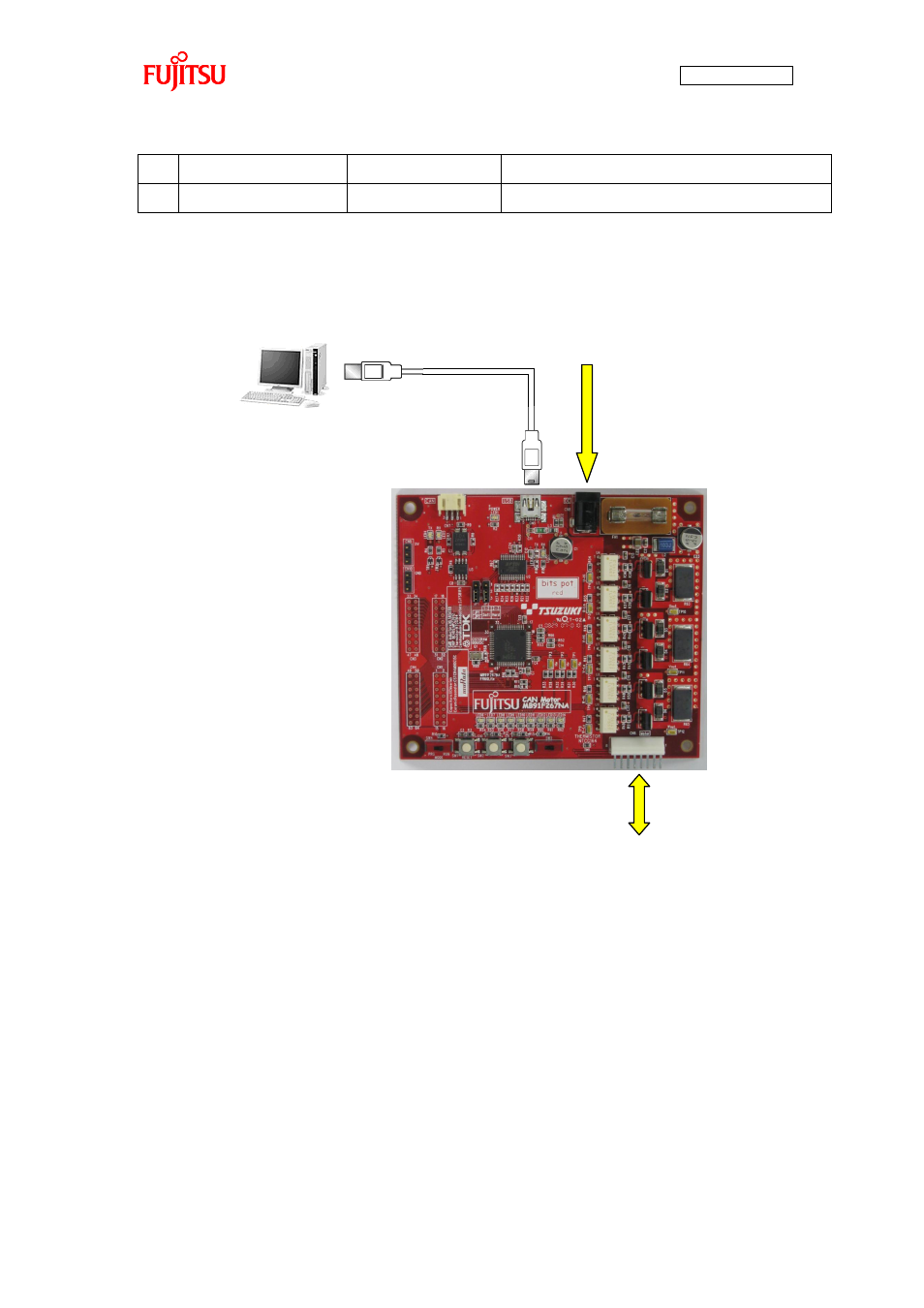
“Figure 1-2 System connection diagram” shows the connection of the system.
Figure 1-2 System connection diagram
Connect the PC with the board by using the USB cable included in the kit.
The power is supplied to the board from the USB bus power.
Directly connect the USB port to that on the PC. Do not make the connection via a USB hub.
AC adapter (accessory)
* Prepare the PC by yourself.
BLDC motor (accessory)
Use the AC adapter included in the
kit for the connection. (The motor
power is supplied from the AC
adapter.)
Use the USB cable included in the kit for
the connection. (The power is supplied
from the USB bus power.)
- XG Series P3NK-4452-01ENZD (614 pages)
- FPCAC14C (1 page)
- MCJ3230SS (161 pages)
- MBA3073NC (138 pages)
- T5140 (102 pages)
- T5140 (76 pages)
- MAM3367MC/MP (152 pages)
- MPC3045AH (185 pages)
- MB2142-02 (23 pages)
- MB15F86UL (6 pages)
- MHS2030AT (40 pages)
- MHW2100BS (296 pages)
- MHK2060AT (227 pages)
- Disk Drives MHK2060AT (227 pages)
- MCM3064SS (170 pages)
- Mainboard D1561 (45 pages)
- MHC2040AT (219 pages)
- D1961 (45 pages)
- DISK DRIVES MHM2100AT (231 pages)
- MHR2010AT (250 pages)
- MHZ2120BJ (320 pages)
- MCE3064AP (175 pages)
- LQFP-64P (16 pages)
- Solaris PCI GigabitEthernet 3.0 (115 pages)
- MAY2036RC (94 pages)
- MAB3091 (142 pages)
- MPE3XXXAT (191 pages)
- MHV2040AH (40 pages)
- MHW2040AC (278 pages)
- ETERNUSmgr P2X0-0202-01EN (64 pages)
- VSS Hardware Provider 2.1 (134 pages)
- MAG3182FC (61 pages)
- MAU3147NC/NP (130 pages)
- MAX3147RC (94 pages)
- MHV2160BT (296 pages)
- MHV2040AT (280 pages)
- MAW3300NC/NP (130 pages)
- DeskPower E623 (50 pages)
- MAG3182LC (133 pages)
- OPTICAL DISK DRIVES MDG3064UB (42 pages)
- MHF2021AT (225 pages)
- MHR2040AT (40 pages)
- Single Drive FTM7926FB (1 page)
- PG-FCS103 (98 pages)
- MAS3735FC (114 pages)