17 osd control buttons, Table 4-11: rs232 serial connector pinouts, Table 4-12: osd control button jp1 pinouts – IEI Integration DM_Series v1.14 User Manual
Page 87: Table 4-13: osd control button jp2 pinouts, See table 4-11 and figure 4-10, Dm series industrial monitor page 87
DM Series Industrial Monitor
Page
87
5 GND
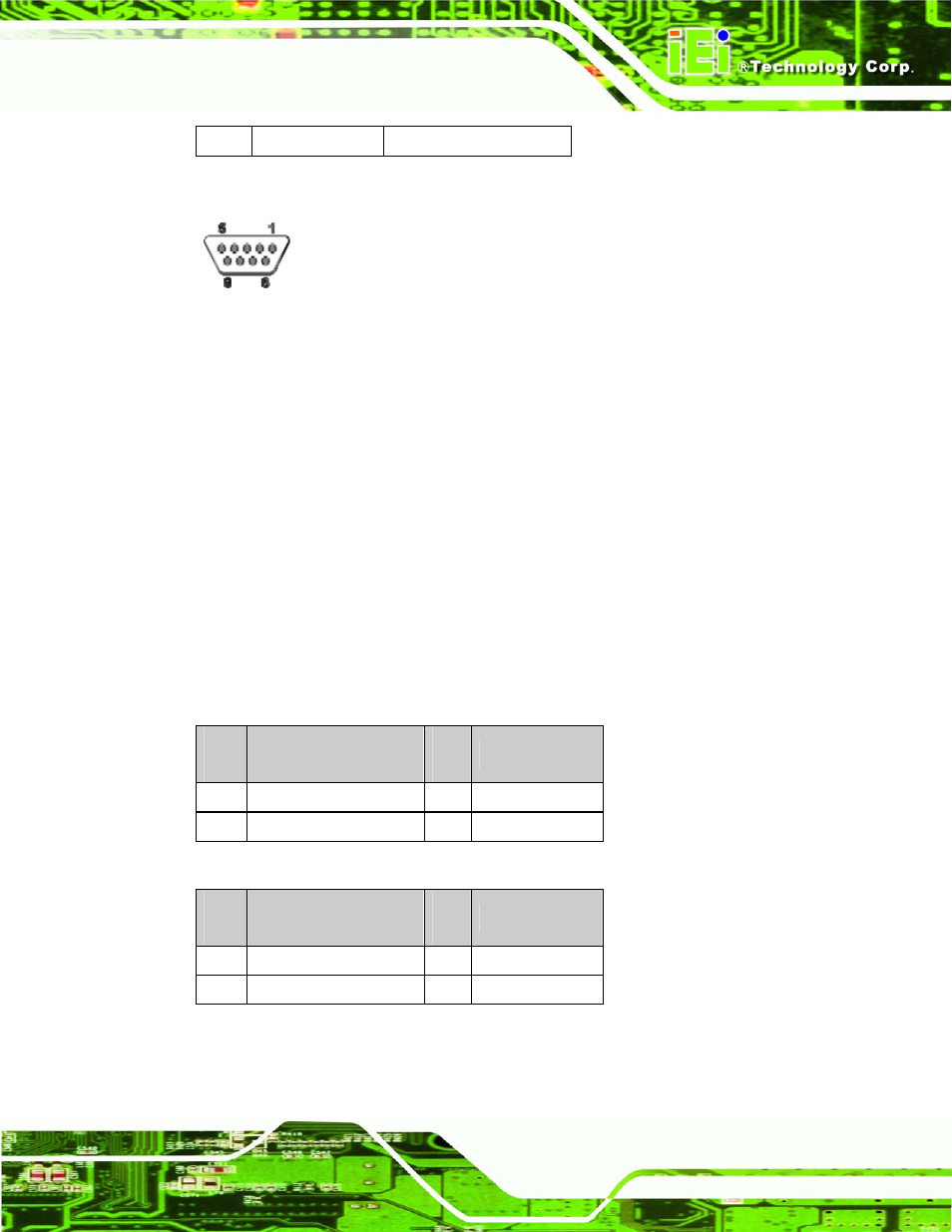
Table 4-11: RS232 Serial Connector Pinouts
Figure 4-10: RS232 Serial Connector Pinout Locations
4.2.17 OSD Control Buttons
CN Label:
JP1, JP2, JP3, JP4
CN Type:
Pushbutton
CN Pinouts:
See Table 4-12, Table 4-13, Table 4-14, Table 4-15
CN Location:
Use these buttons to control the OSD functions. The following tables list each button’s
function and pinouts.
PI
N
DESCRIPTION
PI
N
DESCRIPTION
1 MENU/SELECT
3 No
Connect
2 Ground
4 No
Connect
Table 4-12: OSD Control Button JP1 Pinouts
PI
N
DESCRIPTION
PI
N
DESCRIPTION
1 UP/COLOR
ADJUST 3 No
Connect
2 Ground
4 No
Connect
Table 4-13: OSD Control Button JP2 Pinouts