14 vga connector, Figure 4-35: vga connector location, Table 4-42: vga connector pinouts – IEI Integration DM_Series v1.14 User Manual
Page 118
DM Series Industrial Monitor
Page 118
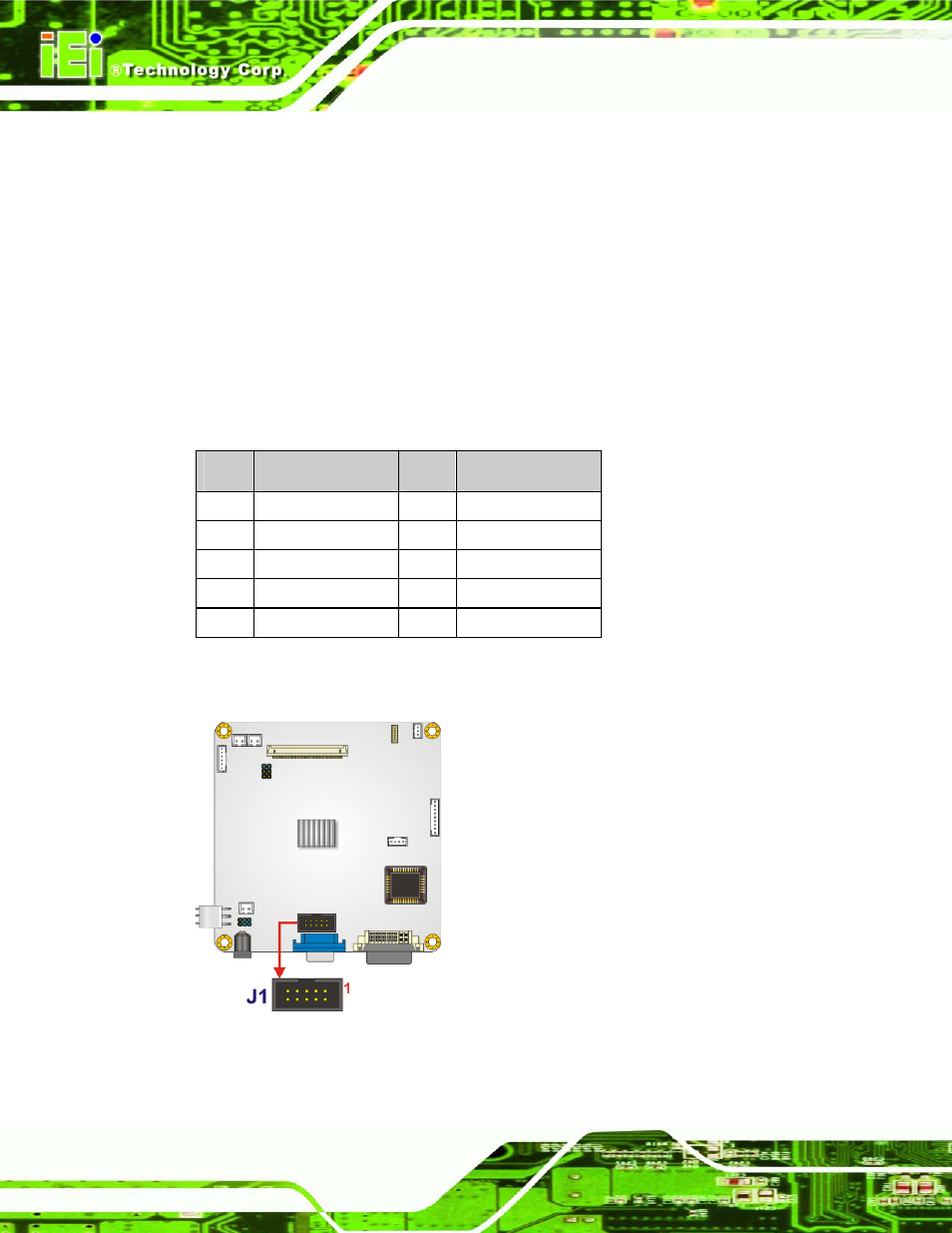
4.4.14 VGA Connector
CN Label:
J1
CN Type:
10-pin box header
CN Pinouts:
CN Location:
In addition to the standard DB-15 female VGA connector (J1), a VGA connection can also
be made through the on-board CN2 10-pin header.
PIN
DESCRIPTION
PIN
DESCRIPTION
1 RED
2 SMCLK
3 GREEN
4 SMDATA
5 BLUE
6 GROUND
7 HSYNC
8 GROUND
9 VSYNC
10
GROUND
Table 4-42: VGA Connector Pinouts
Figure 4-35: VGA Connector Location