Motorola DSP96002 User Manual
Page 96
7 - 10
DSP96002 USER’S MANUAL
MOTOROLA
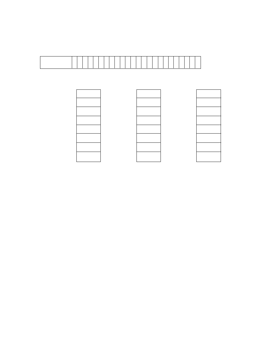
31 24 23 16 15 8 7 0 PSR
X X X X X X X X Y Y Y Y Y Y Y Y P P P P P P P P Port Select
* 7 6 5 4 3 2 1 0 7 6 5 4 3 2 1 0 7 6 5 4 3 2 1 0 Register
X:$FFFFFFFC
* - reserved, read as zeros, should be written with
zeros for future compatibility.
X
Y
P
$FFFFFF7F $FFFFFFFF $FFFFFFFF
X7 Y7 P7
$E0000000 $E0000000 $E0000000
X6 Y6 P6
$C0000000 $C0000000 $C0000000
X5 Y5 P5
$A0000000 $A0000000 $A0000000
X4 Y4 P4
$80000000 $80000000 $80000000
X3 Y3 P3
$60000000 $60000000 $60000000
X2 Y2 P2
$40000000 $40000000 $40000000
X1 Y1 P1
$20000000 $20000000 $20000000
X0 Y0 P0
$00000800 $00000800 $00000400
or or or
$00000200 $00000200 $00000000
Note:
X and Y Data Memories lowest external address determined by DE bit in the OMR register. P
Memory lowest external address determined by MA, MB and MC bits in the OMR register.
Figure 7-6. DSP96002 Port Select Register (PSR)
ment that is defined as internal remains internal. The Port Select Register format is shown in Figure 7-6 and
is described below.
7.3.1.1
PSR Program Memory Port Select (P0-P7) Bits 0-7
The Program Memory Port Select control bits (P0-P7) determine the assignment of the 8 Program Memory
segments to Port A or B. If the segment bit is cleared, the Program Memory segment is assigned to Port A.
If the segment bit is set, the memory segment is assigned to Port B. The memory segment to control bit
correlation is shown in Figure 7-6. For example, if the P4 bit is set, then all memory traffic for addresses
P:$80000000 to P:$9FFFFFFF will go thorough Port B. During hardware reset, the P0-P7 bits are cleared
if the MODA pin was hold low when negating
—
R
—
E
—
S
—
E
–
T. P0-P7 are set if the MODA pin was hold
high when negating
—
R
—
E
—
S
—
E
–
T.
7.3.1.2
PSR Y Data Memory Port Select (Y0-Y7) Bits 8-15
The Y Data Memory Port Select control bits (Y0-Y7) determine the assignment of the 8 Y Data Memory seg-
ments to Port A or B. If the segment bit is cleared, the Y Data Memory segment is assigned to Port A. If the
segment bit is set, the memory segment is assigned to Port B. The memory segment to control bit correla-
tion is shown in Figure 7-6. For example, if the Y4 bit is set, then all memory traffic for addresses
Y:$80000000 to Y:$9FFFFFFF will go thorough Port B. During hardware reset, the Y0-Y7 bits are cleared.