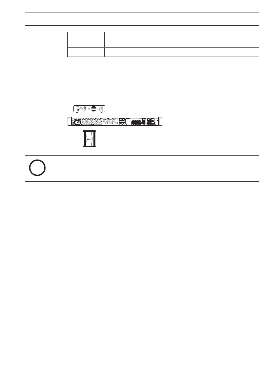
Figure 22.9: loop configuration for ch a and ch b – Telex RTS OMS OMNEO Main Station Advanced Digital Partyline Intercom Base (5-Pin Female) User Manual
Page 105

OMS OMNEO Main Station
Configuration | Ports menu | en
105
Bosch Security Systems, LLC
Technical Manual
01-2021 | 03 | F.01U.380.820
Unbalanced
Audio
uses ground reference signaling
Balanced Audio
uses differential signaling
By default, this field is set to Off.
Loop Field
Use the
Loop
field to configure a pair of ports to act as a loop in and loop out connectors. CH
B can be configured as a loop out connector for CH A. Additionally; CH D can be configured as
a loop out connector for CH C.
Configuring a pair of connectors for looping allows greater flexibility when installing the 2-Wire
wiring.
1
2
RTS
Monitor
Power
PS-20 Power Supply
PGM
Select
PGM
Level
4ch
2
4
2
4
2ch 1
2
1
2
U N IVER S AL
B ELTPACK
-5000
B P
Figure 22.9:
Loop configuration for CH A and CH B
i
Notice!
When XLR-A and XLR-B are looped, this means both connectors are supporting the same pair
of RTS-1 and RTS 2 channels and these ports to the intercom are port CH A and port CH B.
Auto-Mute Field
Use the
Auto-Mute
field to determine whether the 2W port automatically mutes. If the setting
is enabled, the 2W port is muted whenever OMS detects the absence of DC power on the line
(typically, because the cable on the 2W port was removed).
By default, the Auto-Mute is enabled.
