ProSoft Technology MVI71-DFNT User Manual
Page 76
Reference
MVI71-DFNT ♦ PLC 5
User Manual
EtherNet/IP Client/Server Communication Module
Page 76 of 175
ProSoft Technology, Inc.
February 3, 2011
5.2.4 Data Flow between MVI71-DFNT Module and PLC Processor
The following discussion outlines the flow of data between the two pieces of
hardware (PLC processor and MVI71-DFNT module) and other nodes on the
TCP/IP network under the module’s different operating modes. The module
contains both servers and a Client.
The following topics discuss the operation of the server and Client drivers.
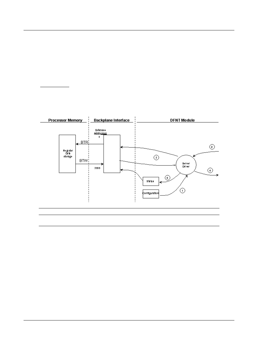
The Server Driver allows the MVI71-DFNT module to respond to data read and
write commands issued by clients on the Ethernet/IP network using explicit
messaging. The following flow chart and associated table describe the flow of
data into and out of the module.
Server Driver
Step
Description
1
The server driver receives the configuration information from the configuration file on the
Compact Flash Disk, and the module initializes the servers.
2
A Host device, such as a ControlLogix processor, RSLinx or an HMI application issues a
read or write command to the module. The server driver qualifies the message before
accepting it into the module.
3
After the module accepts the command, the data is immediately transferred to or from
the internal database in the module. If the command is a read command, the data is read
out of the database and a response message is built. If the command is a write
command, the data is written directly into the database and a response message is built.
4
After the data processing has been completed in Step 3, the response is issued to the
originating master node.
5
Status data for the servers is passed to the processor under ladder logic control using
the command control data area in the M1 file.