ProSoft Technology MVI71-DFNT User Manual
Page 72
Reference
MVI71-DFNT ♦ PLC 5
User Manual
EtherNet/IP Client/Server Communication Module
Page 72 of 175
ProSoft Technology, Inc.
February 3, 2011
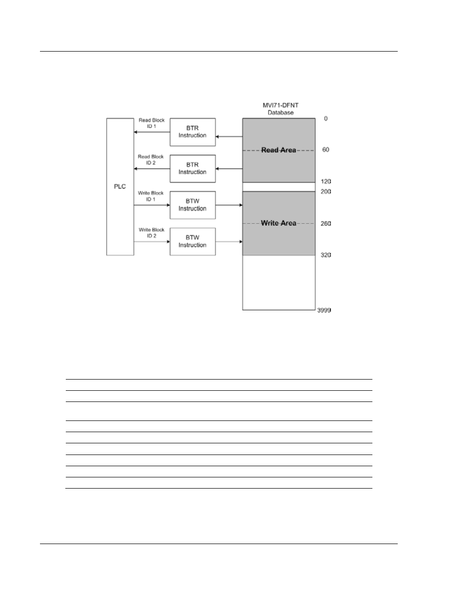
The Read Data Area will be transferred from the module to the PLC processor.
The Write Data Area will be transferred from the PLC processor to the module.
The following example shows the resulting data flow:
5.2.3 Module Control Blocks
Specific write block IDs are reserved for module control operations. These blocks
request that the module perform specific tasks. The following write blocks are
valid for module control.
Block ID
Definition
250 and 251
Status data request and response blocks
1000 to 1066
Blocks used to initialize the module’s database with values in the processor on
startup.
2000
Request and respond with command list error data for a set of commands.
3000
Set the enable code for a set of commands to 0 to disable polling.
3001
Set the enable code for a set of commands to 1 to enable polling.
3002
Set the enable code for a set of commands to 2 to enable conditional polling.
9998
Request block to warm boot the module
9999
Request block to cold boot the module