ProSoft Technology MVI71-DFNT User Manual
Page 150
Reference
MVI71-DFNT ♦ PLC 5
User Manual
EtherNet/IP Client/Server Communication Module
Page 150 of 175
ProSoft Technology, Inc.
February 3, 2011
Complete the dialog box for the data area to be transferred. CIP Data Table
messages require a tag database element for both the source and destination.
The
D
ESTINATION
T
AG
is a tag defined in the ControlLogix Tag database. The
S
OURCE
E
LEMENT
is the tag element in the DFNT module. The module simulates
a tag database as an array of elements defined by the maximum register size for
the module (user configuration parameter "Maximum Register" in the [Module]
section) with the tag name
INT
_
DATA
.
In the example above, the first element in
the database is the starting location for the read operation of ten elements.
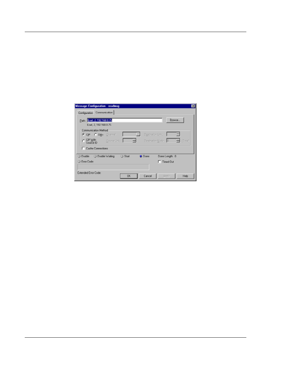
Additionally, the
C
OMMUNICATION
information must also be configured. An
example of the dialog box follows:
Verify that the
CIP
radio-button is selected as the
C
OMMUNICATION
M
ETHOD
. The
P
ATH
specifies the message route from the ControlLogix processor to the DFNT
module. Path elements are separated by commas. In the example path shown,
the first element is "Enet", which is the user-defined name given to the 1756-
ENET module in the chassis (you could substitute the slot number of the ENET
module for the name), the second element, "2", represents the Ethernet port on
the 1756-ENET module, and the last element of the path, "192.168.0.75", is the
IP address of the DFNT module, the target for the message.
More complex paths are possible if routing to other networks using multiple 1756-
ENET modules and racks. Refer to the Rockwell Automation Support
Knowledgebase for more information on Ethernet routing and path definitions.