0 me-ags-n module setup, 1 confi guring the internal me-ags-n settings – Magnum Energy AGS Network (ME-AGS-N) User Manual
Page 25
19
© 2012 Magnum Energy, Inc.
3.0 ME-AGS-N Module Setup
3.0 ME-AGS-N Module Setup
This section covers the AGS’s internal settings and how to configure them.
3.1 Confi guring the Internal ME-AGS-N Settings
Unscrew the AGS module’s four top screws and remove the plastic cover to
access the Input DC Voltage Jumper and the 4-position DIP (Dual In-line Pack-
age) switch (Figure 3-1).
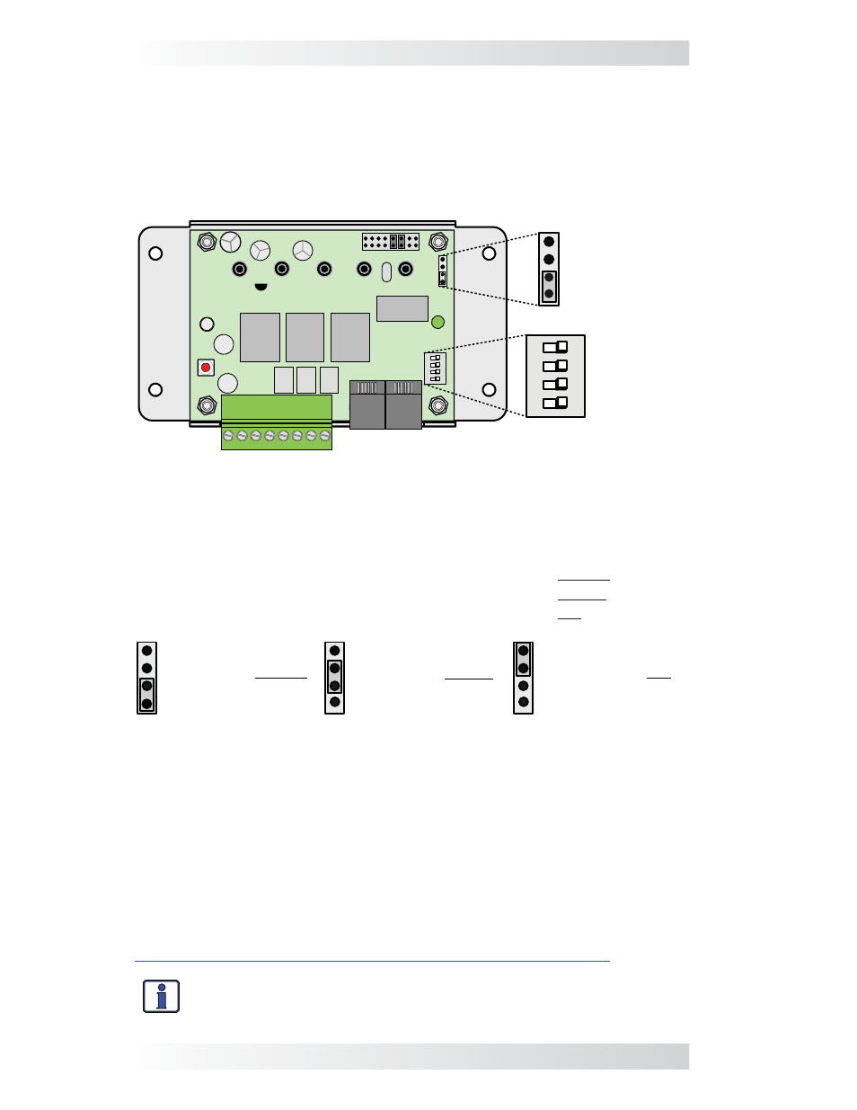
Figure 3-1, Inside the ME-AGS-N Module
Input DC Voltage Jumper Setting – This setting is determined by connecting
two small pins with a small, black plastic box (i.e., jumper). This setting can be
confi gured for 12, 24 or 48 VDC operation (Figure 3-2), which is determined
by the nominal DC voltage connected to Terminals #3 and #4 on the AGS.
•
For 12-volt DC operation, position the jumper on the bottom two pins.
•
For 24-volt DC operation, position the jumper on the middle two pins.
•
For 48-volt DC operation, position the jumper on the top two pins.
Input DC
Voltage
Jumper
Setting
(Default: 12V
Setting)
ON
4
3
2
1
DIP Switch
Gen Type
Setting
(Default: QD
Mode Setting)
12/24/48V
12/24/48V
ON
4
3
2
1
13
4
2
RY1
RY2
RY3
12 VDC Operation
(jumper on bottom
two pins)
**default setting**
24 VDC Operation
(jumper on middle
two pins)
48 VDC Operation
(jumper on top
two pins)
Figure 3-2, DC Voltage Settings
DIP Switch Gen Type Setting – The Gen Type setting is determined by a
DIP switch, which is actually four small switches that can be turned to the ON
or OFF positions. The position of each of these switches is used to determine
the open and close timing sequence for the three internal AGS relays (RY1,
RY2 and RY3). The multiple positions of the DIP switch allow a wide range of
generator start/stop circuit confi gurations.
After determining the appropriate start/stop timing sequence for your
generator, use Table 3-1 to determine the correct Gen Type setting for your
generator’s start/stop requirements.
For examples and further assistance, view the generator wiring diagrams at:
http://www.magnumenergy.com/service/genwiringdiagrams.htm
.
Info: This switch is shipped with a thin yellow plastic fi lm covering.
You can just punch through this thin fi lm to set your gen type.