Ry2 ry3, Relays inside the ags controller, 0 installation – Magnum Energy AGS Network (ME-AGS-N) User Manual
Page 20
2.0
Installation
© 2012 Magnum Energy, Inc.
14
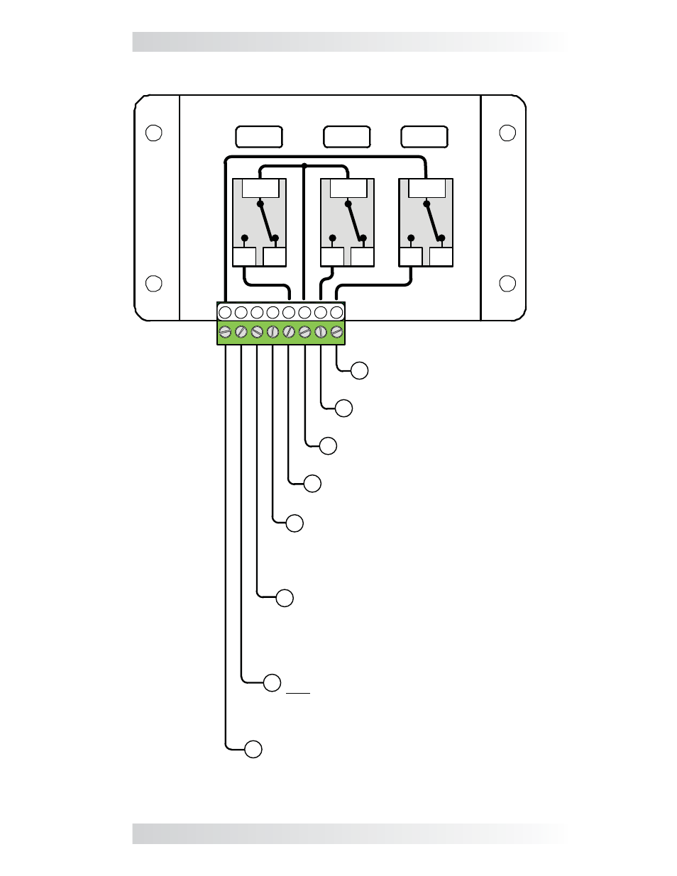
Figure 2-11, Wiring to the ME-AGS-N Module’s Terminal Block
1
2 3 4 5 6 7 8
RY1
NC
COM
NO
NC
COM
NO
NC
COM
NO
Positive DC voltage input
[positive terminal from monitored
battery bank (8.5 to 70 volts DC from
the positive terminal of the monitored
battery bank); negative side is
connected to Terminal #4]
Negative DC voltage input
[negative terminal from monitored battery
bank (positive side connected to Terminal 3),
and the negative side of the run sense signal
(positive side connected to Terminal 2)]
Positive run sense input (10 to 40 volts DC
only when generator is running; negative
side is connected to Terminal #4)
Not required if Gen Type setting is 2-Wire
Standby mode
Common (COM) contact on Relay 3 (RY3)
Normally Open (N.O.)
contact on Relay 3 (RY3)
Common (COM) contact on
Relay 1 (RY1) and Relay 2 (RY2)
Normally Open (N.O.)
contact on Relay 2 (RY2)
Normally Open (N.O.) contact
on Relay 1 (RY1)
8
7
1
2
3
4
5
6
RY2
RY3
Relays inside the AGS controller