2 required materials and tools (not included), 3 mounting procedure, 0 installation – Magnum Energy AGS Network (ME-AGS-N) User Manual
Page 12
2.0
Installation
© 2012 Magnum Energy, Inc.
6
2.2 Required Materials and Tools (not included)
To properly install the AGS module you will need to supply the following:
Required Materials
• 16 to 12 AWG wire for connecting the AGS to the generator start/stop
circuit and to the battery bank
• In-line fuse holders (with a 5-amp DC fuse)
Required Tools
• Phillips screwdriver (#2)
• Flat-blade screwdrivers
(1/4” and 1/8” blades)
• DC voltmeter
• Cut-out tool (knife/saw)
• Drill bits (7/64” & 1/8”)
• Drill
• Wire stripper
• Pencil
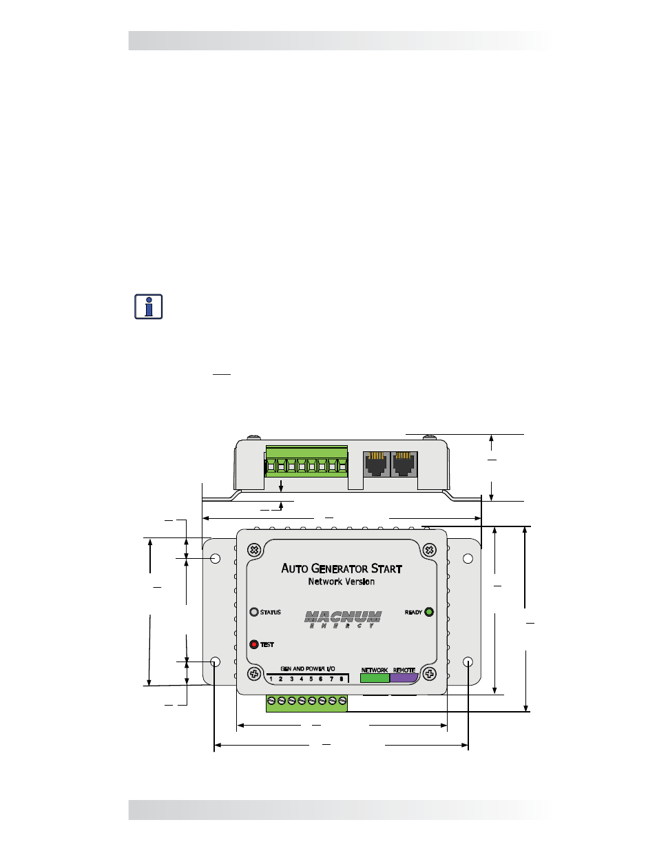
2.3 Mounting Procedure
Select an inside mounting location that is clean, dry, and protected from
extreme temperatures. Refer to Figure 2-2 for the AGS module’s dimensions.
Info: The AGS module can be mounted in any direction. However,
be sure to allow ample room to access the 8-port terminal block, and
the NETWORK and REMOTE ports.
1. Remove the 8-port terminal block from the module (Figure 1-1, Item
3). The terminal block is friction-fi t, remove by pulling it straight out.
Note: Do not plug the terminal block back into the AGS module until
the installation is complete and you are ready to perform the functional
tests (per directions in Section 4.0).
2. Mount the AGS module using the supplied #8 x 3/4” screws (x4).
5
8
3 ”
7
8
4 ”
3
4
2
1
4
4 ”
3
8
”
3
8
5 ”
1
4
3 ”
3
8
”
2”
3
16
”
(31.8 mm)
1
4
1 ”
(82.6 mm)
(92.8 mm)
(136.6 mm)
(108 mm)
(123.9 mm)
(9.5 mm)
(50.8 mm)
(69.9 mm)
(9.5 mm)
(4.8 mm)
Figure 2-2, ME-AGS-N Dimensions