5 me-ags-n terminal block wiring connections, 0 installation – Magnum Energy AGS Network (ME-AGS-N) User Manual
Page 16
2.0
Installation
© 2012 Magnum Energy, Inc.
10
2.5 ME-AGS-N Terminal Block Wiring Connections
With the AGS already mounted, remove the green 8-port terminal block before
proceeding with wiring the generator. Refer to Figure 2-11 and the info below
to wire the AGS’s terminal block to the generator.
CAUTION: DO NOT plug in the 8-port terminal block until all the
wiring to the module is complete and you are ready to perform the
functional tests (per instructions in Section 4.0).
CAUTION: A fuse rated at 5 amps or less must be used to protect
all power circuits connected to the AGS (do not fuse ground connec-
tions). Ensure the fuse is correctly rated for the wire size used. Refer
to national and local codes for rating and type. Normally, a minimum
#16 AWG wire is required in order to use a 5-amp fuse.
Info: The green 8-port terminal block accepts CU/AL conductors from
#30 to #12 AWG (0.05 to 3.3 mm
2
).
2.5.1 Power Connections (Terminals 3
&
4)
Terminals #3 (positive) and #4 (negative) on the 8-port terminal block are
connected to the monitored battery bank*. These terminals are used to power
the AGS module and to monitor the inverter’s battery voltage (when used to
autostart the generator based on low battery voltage).
Info: The AGS requires a DC input of 8.5-70 volts in order to operate
the internal relays. An input voltage greater than 70 volts will cause
damage to the AGS and is not covered by the product warranty.
* Monitored Battery Bank – When autostarting the generator based on battery
voltage (i.e., start VDC), the inverter’s battery bank must be connected to Termi-
nals #3 (positive) and #4 (negative). If autostarting based on any other condition
(i.e., temperature, amps, etc.), either the inverter battery bank or the generator’s
battery may be used to power the AGS module. However, the negative terminal
of every battery bank must be connected together to prevent damage to the AGS
(see Section 2.4.4).
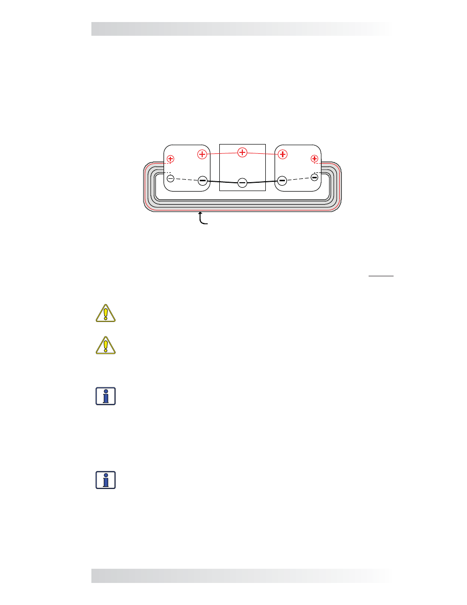
2.4.4 Ensure all Negative Connections are Connected Together
When connecting devices together (via a network communication cable),
the return path (i.e., battery negative) of each battery powered device must
be at the same potential (i.e., electrically common with each other). This
prevents a high-impedance path developing between the connected devices,
which can cause the network cable to become the DC return path to the
battery – possibly resulting in permanent damage to all connected devices
on the network. This also requires that the battery negative connection of
each device be always connected before connecting/disconnecting any bat-
tery positive.
Network cable
Inverter
Battery
Inverter
Battery
AGS
Inverter
Figure 2-9, Connected Devices at the Same Potential