Yaskawa MP3200 Troubleshooting Manual User Manual
Page 108
5.2 Troubleshooting Message Communications
Message Communications Errors
5-33
T
roubleshooting Programming and Debugging
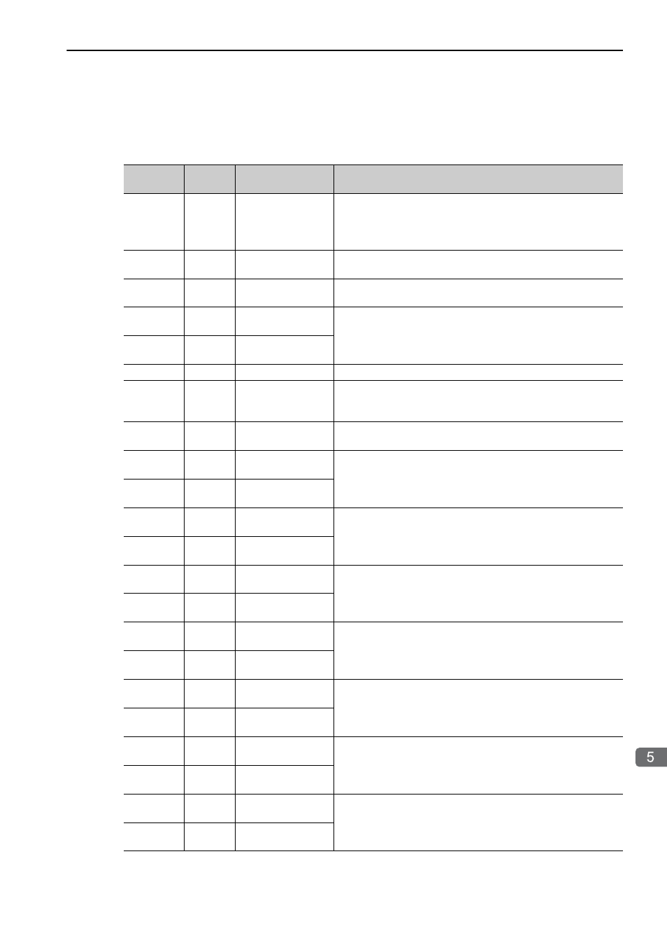
Receive Message Function (MSG-RCVE)
The parameters for the Send Message function are checked according to the following two communica-
tions protocols.
• Parameter List When Pro-Type (Communications Protocol) Is MEMOBUS
Parameter
No.
IN/OUT
*
Item
Description and What to Check
10
IN
Connection number
Set the remote station from which to send the message. (Set the
connection number that is set in the connection parameters.)
Make sure that the setting is within the following setting range.
218IFD: 1 to 20
11
OUT
Option
Gives the optional settings. The meaning of this option depends
on the protocol being used.
12
OUT
Function code
Contains the function code that was requested from the sending
side.
14
OUT
Data address, lower
word
Contains the start address of the data requested from the sending
side.
(Contains the word address for register access, or contains the bit
address for relay or coil access.)
15
OUT
Data address, upper
word
16
OUT
Register type
Contains the register type that was requested by the sending side.
17
OUT
Data size
Contains the size of read or write data that was requested by the
sending side. (Contains the size in words for registers, and in bits
for relays or coils.)
18
OUT
Remote CPU mod-
ule number
Contains the remote CPU number.
20
IN
Coil offset, lower
word
Set the offset to the word address of the coil.
21
IN
Coil offset, upper
word
22
IN
Input relay offset,
lower word
Set the offset to the word address for the input relay.
23
IN
Input relay offset,
upper word
24
IN
Input register offset,
lower word
Set the offset to the word address for the input register.
25
IN
Input register offset,
upper word
26
IN
Holding register off-
set, lower word
Set the offset to the word address for the hold register.
27
IN
Holding register off-
set, upper word
28
IN
Data relay offset,
lower word
Set the offset to the word address for the data relay.
29
IN
Data relay offset,
upper word
30
IN
Data register offset,
lower word
Set the offset to the word address for the data register.
31
IN
Data register offset,
upper word
32
IN
Output coil offset,
lower word
Set the offset to the word address of the output coil.
33
IN
Output coil offset,
upper word
Continued on next page.