Example operations, Fig 3.2 operations in drive mode – Yaskawa G7 Drive User Manual
Page 81
3
-8
Example Operations
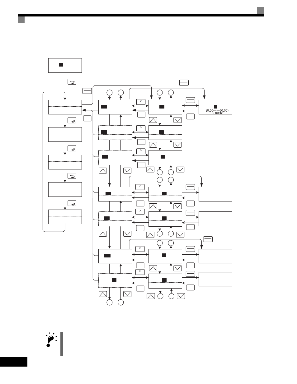
Key operations in drive mode are shown in the following figure.
Fig 3.2 Operations in Drive Mode
Note When changing the display with the Increment and Decrement Keys, the next display after the one for the last parameter number will be the one for the
first parameter number and vise versa. For example, the next display after the one for U1-01 will be U1-40. This is indicated in the figures by the letters
A and B and the numbers 1 to 6.
IMPORTANT
The display for the first monitor parameter (frequency reference) will be displayed when power is turned ON.
The monitor item displayed at startup can be set in o1-02 (Monitor Selection after Power Up).
Operation cannot be started from the mode selection display.
Frequency Ref
-DRIVE-
U1-02=60.00Hz
U1-03=10.05A
** Main Menu **
-DRIVE-
Operation
** Main Menu **
-QUICK-
Quick Setting
** Main Menu **
-ADV-
Programming
** Main Menu **
-VERIFY-
Modified Consts
** Main Menu **
-A.TUNE-
Auto-Tuning
U1-
01
=60.00Hz
Monitor
-DRIVE-
U1-02=60.00Hz
U1-03=10.05A
U1
- 01=60.00Hz
MENU
ESC
DATA
ENTER
Frequency Ref
-DRIVE-
U1-02=60.00Hz
U1-03=10.05A
U1-
01
=60.00Hz
Frequency Ref
-DRIVE-
U1 -01=
0
60.00Hz
MENU
MENU
MENU
MENU
RESET
DATA
ENTER
ESC
DATA
ENTER
Monitor Display
Frequency Setting Display
Mode Selection
Display
Display at Startup
Fault Trace
-DRIVE-
U2-02= OV
U2-03=60.00Hz
U2
- 01=OC
Fault History
-DRIVE-
U3-02= OV
U3-03= OH
U3
- 01= OC
Output Freq
-DRIVE-
U1-04= 2
U1-03=10.05A
U1-
02
=60.00Hz
FAN Elapsed Time
-DRIVE-
U1-01=60.00Hz
U1-02=60.00Hz
U1-
40
= 10H
1
2
1
2
Last Fault
-DRIVE-
U3-02=OV
U3-03=OH
U3 -
01
= OC
Fault Message 2
-DRIVE-
U3-03= OH
U3-04= UV
U3 -
02
= OV
RESET
ESC
5
6
5
6
A
B
A
B
Current Fault
-DRIVE-
U2-02=OV
U2-03=60.00Hz
U2 -
01
= OC
Last Fault
-DRIVE-
U3-03=60.00Hz
U3-04=60.00Hz
U2 -
02
= OV
3
4
3
4
RESET
ESC
U2 - 01= OC
U2 - 02= OV
Over Current
DC Bus Overvolt
DATA
ENTER
ESC
DATA
ENTER
ESC
U3 - 01= OC
Over Current
DATA
ENTER
ESC
U3 - 02= OV
DC Bus Overvolt
DATA
ENTER
ESC
The fault name will be
displayed if the DATA/ENTER
Key is pressed while a constant
is being displayed for which a
fault code is being displayed.
Rdy
Rdy
Rdy
Rdy
Rdy
Rdy
Rdy
Rdy
Rdy
Rdy
Rdy
Rdy
The Frequency Setting
Display will not be
displayed when using an
analog reference.
ESC
Monitor
-DRIVE-
U1-04= 2
U1-03=10.05A
U1
- 02=60.00Hz
Rdy
RESET
ESC
Monitor
-DRIVE-
U1-01=60.00Hz
U1-02=60.00Hz
U1
- 40
= 10H
Rdy
RESET
ESC
Rdy
Rdy
Rdy
Fault Trace
-DRIVE-
U3-03=60.00Hz
U3-04=60.00Hz
U2
- 02 = OV
Rdy
RESET
ESC
Fault Message 2
-DRIVE-
U3-03= OH
U3-04= UV
U3 -
02
= OV
Rdy
RESET
ESC
DATA
ENTER