Yaskawa G7 Drive User Manual
Page 119
5
-8
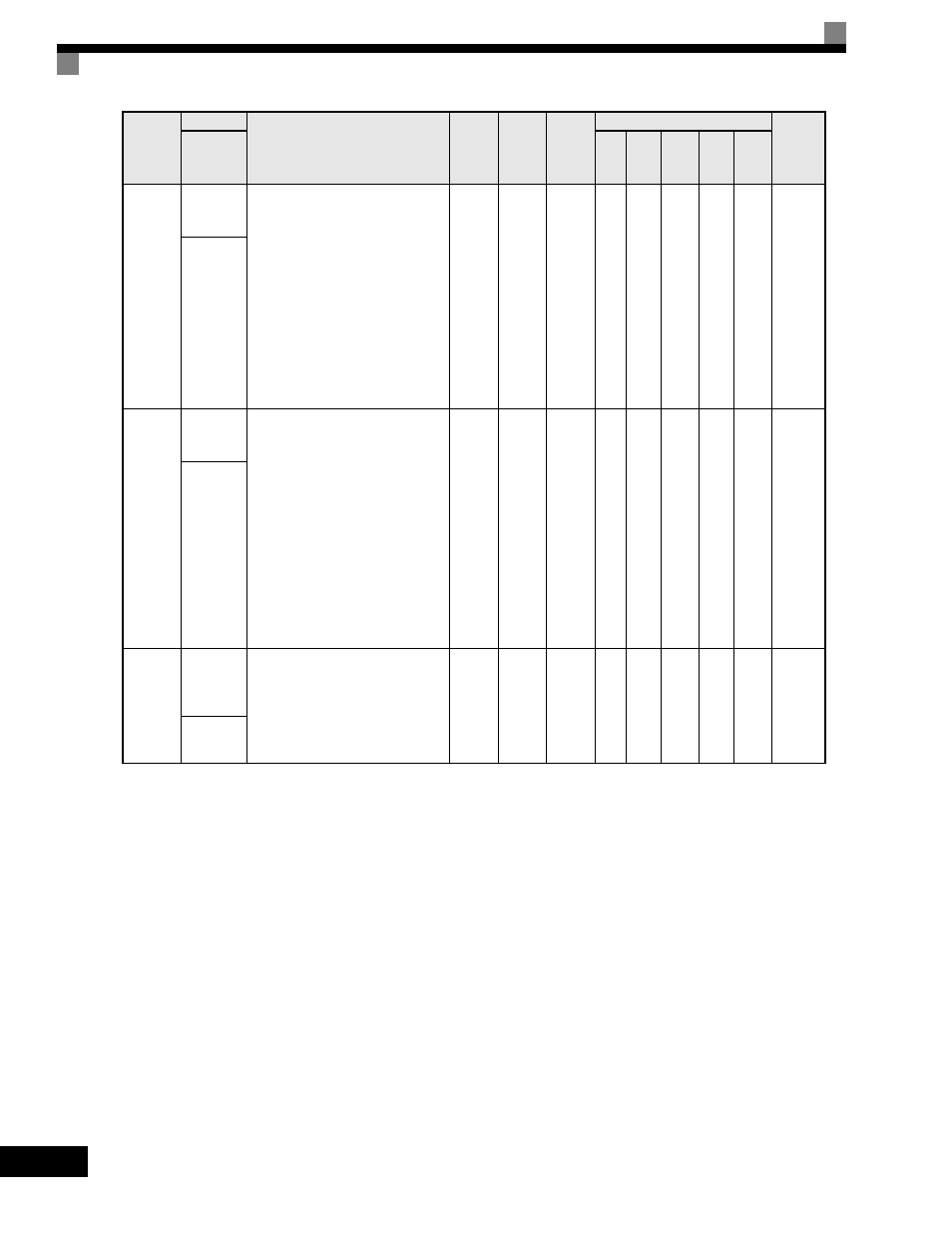
H4-02
Terminal
FM Gain
Setting
Sets terminal FM output level when
selected monitor is at 100%.In order to
adjust the meter, 100% of the
appropriate output is multiplied for the
gain setting, the bias amount is added
and then output.
See H4-02 when stopped in Quick,
Advanced, or Verify mode. If 03
appears on the setting screen, then
terminal FM is used.
See H4-04 when stopped in Quick,
Advanced, or Verify mode. If 06
appears on the setting screen, then
terminal AM is used.
0.00
to
1000.0
100%
Yes
Q
Q
Q
Q
Q
41EH
Terminal
FM Gain
H4-05
Terminal
AM Gain
Setting
Sets terminal AM output voltage (in
percent of 10Vdc) when selected
monitor is at 100% output. In order to
adjust the meter, 100% of the
appropriate output is multiplied for the
gain setting, the bias amount is added
and then output.
See H4-02 when stopped in Quick,
Advanced, or Verify mode. If 03
appears on the setting screen, then
terminal FM is used.
See H4-04 when stopped in Quick,
Advanced, or Verify mode. If 06
appears on the setting screen, then
terminal AM is used.
0.00
to
1000.0
50%
Yes
Q
Q
Q
Q
Q
421H
Terminal
AM Gain
L1-01
Motor
Overload
Protection
Selection
Sets the motor thermal overload
protection (OL1) based on the cooling
capacity of the motor.
0: Disabled
1: Standard Fan Cooled (< 10:1 motor)
2: Standard Blower Cooled (
≥
10:1 motor)
3: Vector Motor (
≤
1000:1 motor)
0 to 3
1
No
Q
Q
Q
Q
Q
480H
MOL Fault
Select
Parameter
Number
Name
Description
Setting
Range
Factory
Setting
Change
during
Operation
Control Methods
MODBUS
Register
Display
V/f
V/f
with
PG
Open
-loop
Vector
1
Flux
Vector
Open
Loop
Vector
2