Yaskawa G7 Drive User Manual
Page 153
5
-42
F1-05
PG Rotation
Selection
0: Fwd=C.C.W. - Phase A
leads with forward run
command. (Phase B leads
with reverse run command.)
1: Fwd=C.W. - Phase B
leads with forward run
command. (Phase A leads
with reverse run command.)
0 or 1
0
No
No
A
No
A
No
384H
PG Rotation
Sel
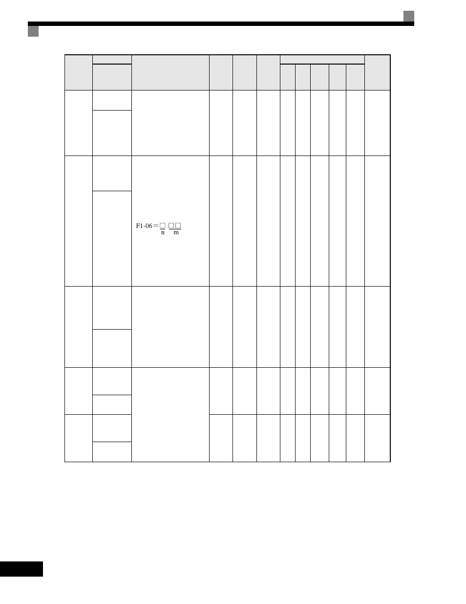
F1-06
PG division
rate (PG
pulse
monitor)
Sets the division ratio for the
pulse monitor of the PG-B2
encoder feedback option
board. This function is not
available with the PG-X2
option board.
Division ratio = (1+ n) /m
(where n=0 or 1 & m=1 to 32)
The first digit of the value of
F1-06 stands for n, the second
and the third stand for m.
(from left to right).
The possible division ratio
settings are: 1/32
≤ F1-06 ≤ 1.
1
to
132
1
No
No
A
No
A
No
385H
PG Output
Ratio
F1-07
Integral
Function
During
Accel/decel
Selection
Sets integral control during
acceleration/deceleration to
either enabled or disabled.
0: Disabled (The integral
function is not used while
accelerating or
decelerating.)
1: Enabled (The integral
function is used at all
times.)
0 or 1
0
No
No
A
No
No
No
386H
PG Ramp PI/I
Sel
F1-08
Overspeed
Detection
Level
Configures the overspeed
fault (OS) detection.
OS fault will occur, if the
motor speed feedback is
greater than the F1-08 setting
for a time longer than F1-09.
F1-08 is set as a
percentage of the maximum
output frequency (E1-04).
See F1-03.
0
to
120
115%
No
No
A
No
A
A
387H
PG Overspd
Level
F1-09
Overspeed
Detection
Delay Time
0.0
to
2.0
0.0 s
*
No
No
A
No
A
A
388H
PG Overspd
Time
Parameter
Number
Name
Description
Setting
Range
Factory
Setting
Change
during
Operation
Control Methods
MODBUS
Register
Display
V/f
V/f
with
PG
Open
Loop
Vector
1
Flux
Vector
Open
Loop
Vector
2