F5-09 set to 0, F5-09 set to 1, F5-09 set to 2 – Yaskawa G7 Drive User Manual
Page 375
6
-158
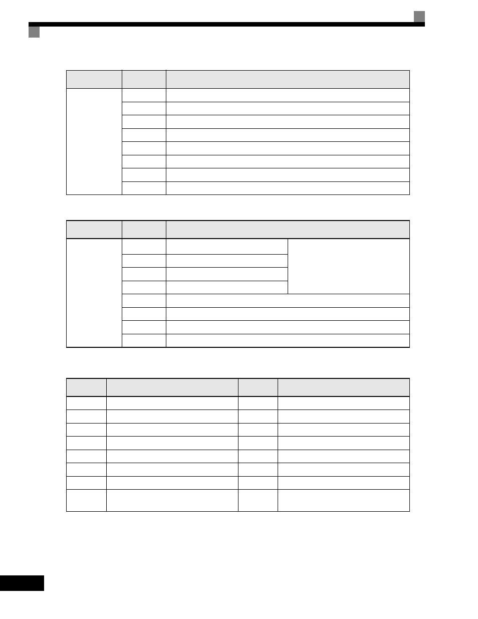
F5-09 Set to 0
F5-09 Set to 1
The following table shows the code outputs.
F5-09 Set to 2
Output depends on the settings in F5-01 to F5-08.
Set Value
Terminal
Number
Output Details
0: 8 separate
outputs
TD5-TD11
Overcurrent (SC, OC, GF)
TD6-TD11
Overvoltage (OV)
TD7-TD11
Drive overload (OL2)
TD8-TD11
Fuse blown (PUF)
TD9-TD11
Overspeed (OS)
TD10-TD11
Drive overheated (OH1) or motor overload (OL1)
TD1-TD2
Zero speed detected
TD3-TD4
Speed agreement
Set Value
Terminal
Number
Output Details
1: Binary code
output
TD5-TD11
bit 0
Encoded output
(Refer to table below)
TD6-TD11
bit 1
TD7-TD11
bit 2
TD8-TD11
bit 3
TD9-TD11
Zero speed detected
TD10-TD11
Speed agreement
TD1-TD2
Operating
TD3-TD4
Minor fault
Bits 3, 2, 1,
and 0
Output Details
Bits 3, 2, 1,
and 0
Output Details
0000
No error
1000
External fault (EFxx)
0001
Overcurrent (SC, OC, GF)
1001
Controller error (CPFxx)
0010
Overvoltage (OV)
1010
Motor overload (OL1)
0011
Drive overload (OL2)
1011
Not used
0100
Drive overheated (OH, OH1)
1100
Power loss (UV1, UV2, or UV3)
0101
Overspeed (OS)
1101
Speed deviation (DEV)
0110
Fuse blown (PUF)
1110
PG open circuit (PGO)
0111
Dynamic braking resistor (RH)
Injection brake transistor error (RR)
1111
Not used