Yaskawa G7 Drive User Manual
Page 167

5
-56
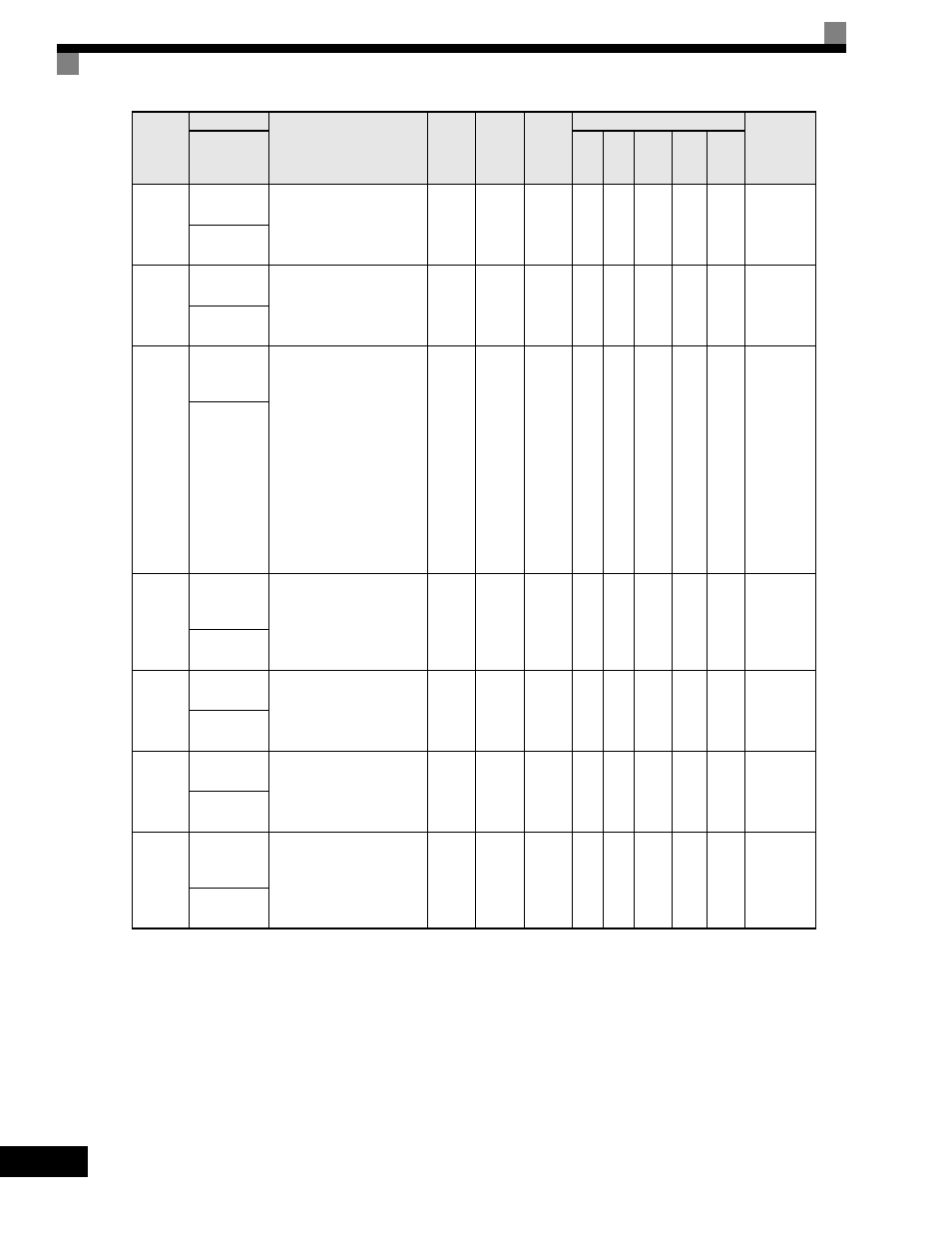
H3-06
Terminal A3
Gain Setting
Sets the output level when
10V is input.
0.0
to
1000.0
100.0%
Yes
A
A
A
A
A
415H
Terminal A3
Gain
H3-07
Terminal A3
Bias Setting
Sets the frequency reference
when 0V is input.
-100.0
to
+100.0
0.0%
Yes
A
A
A
A
A
416H
Terminal A3
Bias
H3-08
Terminal A2
Signal Level
Selection
Selects the signal level of
terminal A2.
0: 0 to 10Vdc (switch S1-2
must be in the OFF
position).
1: -10 to +10Vdc (switch S1-2
must be in the OFF
position).
2: 4 to 20mA (switch S1-2
must be in the ON position)
Note:Switch between current
or voltage inputs by
using (S1-2) switch on
the terminal board.
0 to 2
2
No
A
A
A
A
A
417H
Term A2
Signal
H3-09
Terminal A2
Function
Selection
Selects the function of
terminal A2.
Same choices as Terminal A3
Function Selection (H3-05).
0 to 1F
0
No
A
A
A
A
A
418H
Terminal A2
Sel
H3-10
Terminal A2
Gain Setting
Sets the output level when
10V is input.
0.0
to
1000.0
100.0%
Yes
A
A
A
A
A
419H
Terminal A2
Gain
H3-11
Terminal A2
Bias Setting
Sets the output level when 0V
is input.
-100.0
to
+100.0
0.0%
Yes
A
A
A
A
A
41AH
Terminal A2
Bias
H3-12
Analog Input
Filter Time
Constant
This parameter adjusts the
filter on all 3 analog inputs.
Increase to add stability,
decrease to improve response.
0.00
to
2.00
0.03sec
No
A
A
A
A
A
41BH
Filter Avg
Time
Parameter
Number
Name
Description
Setting
Range
Factory
Setting
Change
during
Operation
Control Methods
MODBUS
Register
Display
V/f
V/f
with
PG
Open
Loop
Vector
1
Flux
Vector
Open
Loop
Vector
2
