Yaskawa G7 Drive User Manual
Page 193
5
-82
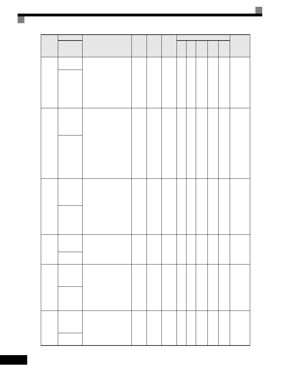
o2-04
Drive/kVA
Selection
Sets the kVA of the Drive.
Enter the number based on
Drive model number. Use the
last four digits of the model
number. CIMR-F7Uxxxx.
This parameter only needs to
be set when installing a new
control board. Do not change
for any other reason. Refer to
Table B.1.
0 to FF
0
*
No
A
A
A
A
A
508H
Drive Model
#
o2-05
Frequency
Reference
Setting
Method
Selection
Determines if the Data/Enter
key must be used to input a
frequency reference from the
Digital Operator.
0: Disabled - Data/Enter key
must be pressed to enter a
frequency reference.
1: Enabled - Data/Enter key is
not required. The frequency
reference is adjusted by the
up and down arrow keys on
the Digital Operator
without having to press the
data/enter key.
0 to 1
0
No
A
A
A
A
A
509H
Operator
M.O.P.
o2-06
Operation
Selection
when Digital
Operator is
Disconnected
Determines if the Drive will
stop when the Digital
Operator is removed when in
LOCAL mode or b1-02=0.
0: Disabled - The Drive will
not stop when the Digital
Operator is removed.
1: Enabled - The Drive will
fault (OPR) and coast to
stop when the Digital
Operator is removed.
0 to 1
0
No
A
A
A
A
A
50AH
Oper
Detection
o2-07
Cumulative
Operation
Time Setting
Sets the initial value of the
elapsed operation timer
U1-13.
0
to
65535
0 hr
No
A
A
A
A
A
50BH
Elapsed Time
Set
o2-08
Cumulative
Operation
Time
Selection
Sets how time is
accumulated for the elapsed
operation timer U1-13.
0: Power-On Time - Time
accumulates when the
Drive is powered.
1: Running Time - Time
accumulates only when
the Drive is running.
0 to 1
0
No
A
A
A
A
A
50CH
Elapsed Time
Run
o2-10
Cumulative
Cooling Fan
Operation
Time Setting
Sets the initial value of the
heatsink fan operation time
monitor U1-40.
0
to
65535
0 hr
No
A
A
A
A
A
50EH
Fan ON Time
Set
Parameter
Number
Name
Description
Setting
Range
Factory
Setting
Change
during
Operation
Control Methods
MODBUS
Register
Display
V/f
V/f
with
PG
Open
Loop
Vector
1
Flux
Vector
Open
Loop
Vector
2