Message format, Slave address, Function code – Yaskawa G7 Drive User Manual
Page 305: Data
6
-88
MODBUS communications can perform the following operations regardless of the settings in b1-01 and b1-02.
•
Monitoring operation status from the PLC
•
Setting and reading parameters
•
Resetting errors
•
Inputting multi-function commands
An OR operation is performed between the multi-function commands input from the PLC and commands
input from multi-function contact input terminals S3 to S7.
Message Format
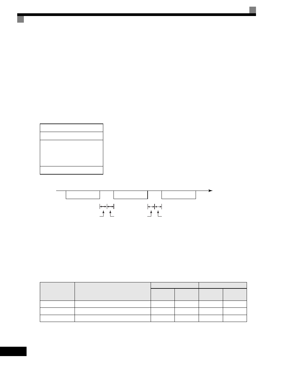
In MODBUS communications, the master sends commands to the slave, and the slave responds. The message
format is configured for both sending and receiving as shown below, and the length of data packets is changed
by the command (function) contents.
The space between messages must support the following.
Fig 6.56 Message Spacing
Slave Address
Set the Drive address from 0 to 32. If you set 0, commands from the master will be broadcast (i.e., the Drive
will not return responses).
Function Code
The function code specifies commands. There are three function codes, as shown below.
Data
Configure consecutive data by combining the storage register address (test code for a loopback address) and
the data the register contains. The data length changes depending on the command details.
Slave address
Function code
Data
Error check
Function Code
(Hexadecimal)
Function
Command Message
Response Message
Min.
(Bytes)
Max.
(Bytes)
Min.
(Bytes)
Max.
(Bytes)
03H
Read storage register contents
8
8
7
37
08H
Loopback test
8
8
8
8
10H
Write multiple storage registers
11
41
8
8
Command message
Response message
Command message
PLC to Inverter
PLC to Inverter
Inverter to PLC
Time (Seconds)
24 bits long
H5-06
setting
24 bits long
5 ms min.