Related parameters, Setting the v/f pattern – Yaskawa G7 Drive User Manual
Page 328
Individual Functions
6-
111
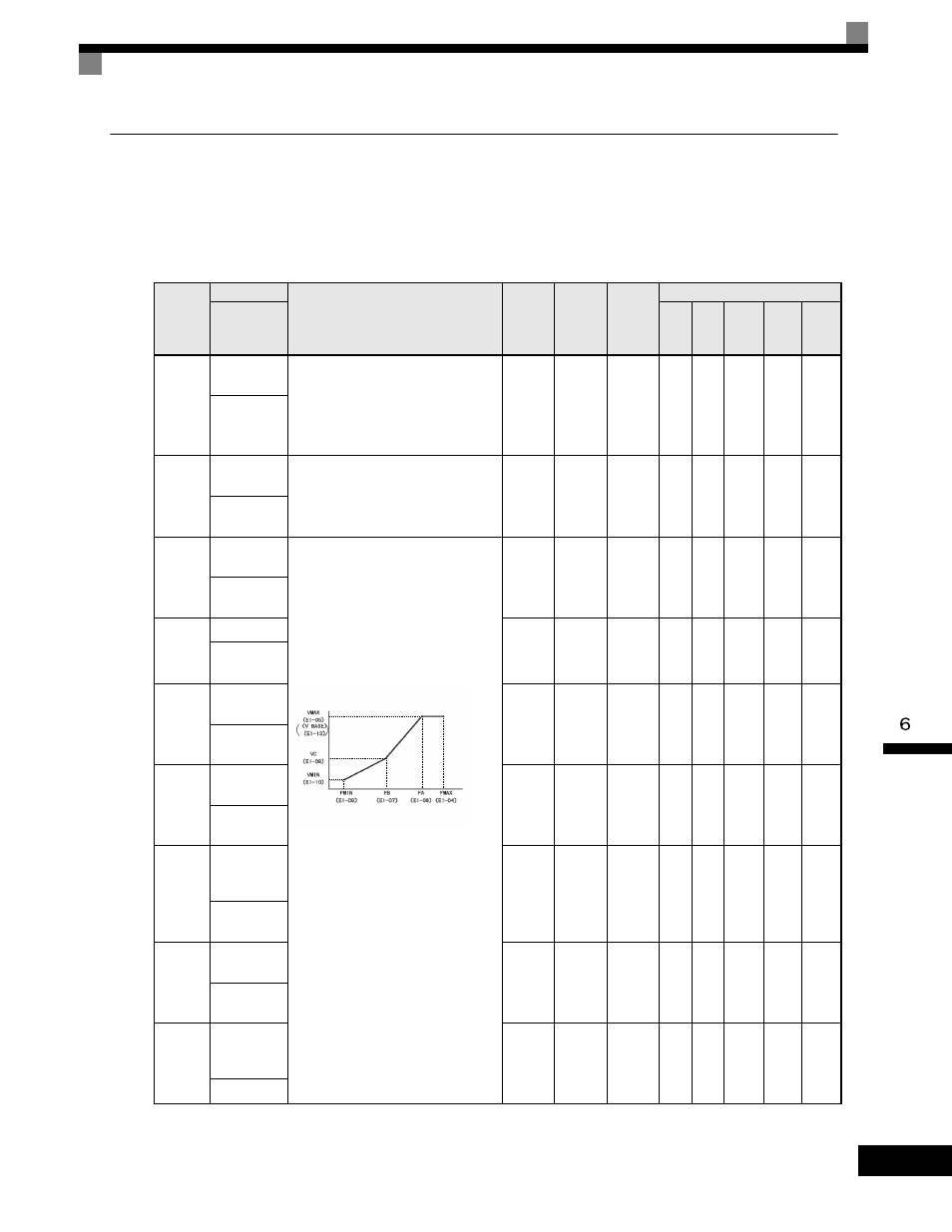
Setting the V/f Pattern
In V/f control method, you can set the Drive input voltage and the V/f pattern as the need arises.
Related Parameters
Parameter
Number
Name
Description
Setting
Range
Factory
Setting
Change
during
Operation
Control Methods
Display
V/f
V/f
with
PG
Open
Loop
Vector
1
Flux
Vector
Open
Loop
Vector
2
E1-01
Input volt-
age setting
Set the Drive input voltage in 1 volt.
This setting is used as a reference value
in protection functions.
155.0 to
255.0
(240V)
310.0 to
510.0
(480V)*1
230.0V
or
460.0V
*1
No
Q
Q
Q
Q
Q
Input Voltage
E1-03
V/f pattern
selection
0 to E: Select from the 15 preset
patterns.
F: Custom user-set patterns (Applicable
for settings E1-04 to E1-10.)
0 to F
F
No
Q
Q
No
No
No
V/F Selec-
tion
E1-04
Max. output
frequency
To set V/f characteristics in a straight
line, set the same values for E1-07 and
E1-09. In this case, the setting for E1-08
will be disregarded.
Always ensure that the four frequencies
are set in the following manner:
E1-04 (FMAX)
≥ E1-06 (FA) > E1-07
(FB)
≥ E1-09 (FMIN)
40.0 to
400.0
*5
60.0Hz
*2
No
Q
Q
Q
Q
Q
Max
Frequency
E1-05
Max. voltage
0.0 to
255.0
*1
230.0V
or
460.0V*
1*2
No
Q
Q
Q
Q
Q
Max Voltage
E1-06
Base
frequency
0.0 to
400.0
*5
60.0Hz
*2
No
Q
Q
Q
Q
Q
Base
Frequency
E1-07
Mid. output
frequency
0.0 to
400.0
3.0Hz
*2
No
A
A
A
No
No
Mid
Frequency A
E1-08
Mid. output
frequency
voltage
0.0 to
255.0
*1
12.6Vac
or
25.3
*1 *2
No
A
A
A
No
No
Mid Voltage
A
E1-09
Min. output
frequency
0.0 to
400.0
*5
0.5Hz
*2
No
Q
Q
Q
A
Q
Min
Frequency
E1-10
Min. output
frequency
voltage
0.0 to
255.0
*1
2.3Vac
or
4.6Vac
*1 *2
No
A
A
A
No
No
Min Voltage
Output voltage (V)
Frequency (Hz)