Using an emergency stop, Related parameters, Using an emergency stop -14 – Yaskawa G7 Drive User Manual
Page 231
6
-14
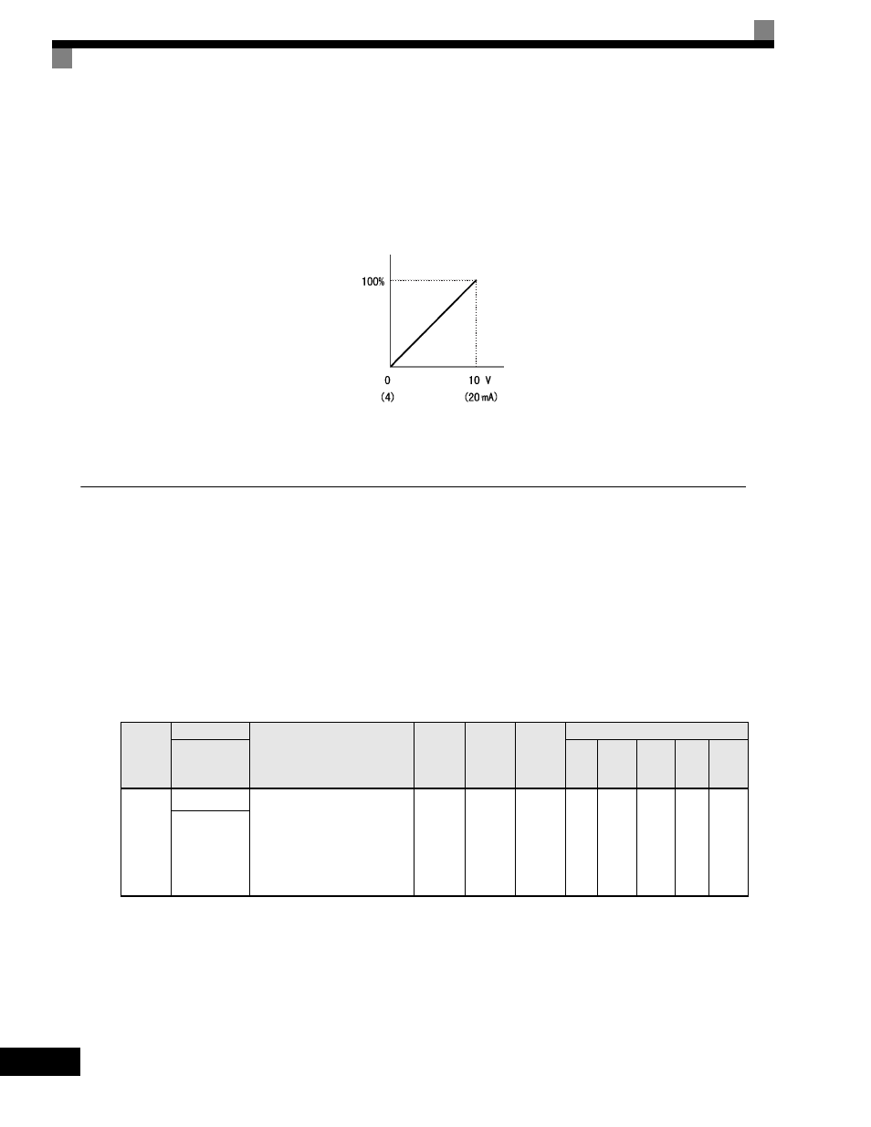
Changing the DC Injection Brake Current Using an Analog Input
If you set H3-09 (Multi-function Analog Input Terminal A2 Function Selection) or H3-05 (Multi-function
Analog Input Terminal A3 Function Selection) to 6 (DC injection brake current), you can change the DC
injection brake current level using the analog input.
At 10Vinput (voltage) or 20mA input (current), 100% of the Drive rated current will be applied.
Fig 6.17 DC Injection Brake Current Using an Analog Input
Using an Emergency Stop
Set a multi-function input terminal (H1-) to 15 or 17 (emergency stop) to decelerate to a stop at the decel-
eration time set in C1-09. If inputting the emergency stop with an NO contact, set the multi-function input ter-
minal (H1-) to 15, and if inputting the emergency stop with an NC contact, set the multi-function input
terminal (H1-) to 17.
After the emergency stop command has been input, operation cannot be restarted until the Drive has stopped.
To cancel the emergency stop, turn OFF the run command and emergency stop command.
Related parameters
* The setting range for accel/decel time will differ depending on C1-10 (Accel/Decel Time Units). If C1-10 is set to "0", then the setting range will change
to 0.00sec to 600.00sec.
Parameter
Number
Name
Description
Setting
Range
Factory
Setting
Change
during
Operation
Control Methods
Display
V/f
V/f with
PG
Open
Loop
Vector
1
Flux
Vector
Open
Loop
Vector
2
C1-09
Fast Stop Time Sets the time to decelerate from
maximum frequency to zero for
the multi-function input "Fast
Stop" function.
Note: this parameter is also used
by selecting "Fast Stop" as a Stop
Method when a fault is detected.
0.0 to
6000.0
*
10.0sec
No
A
A
A
A
A
Fast Stop Time
DC injection brake voltage level
Drive rated current