Frequency voltage – Yaskawa G7 Drive User Manual
Page 212
User Parameter Tables
5-
101
Table 5.6 lists the factory settings of V/F patterns when open loop vector or flux vector control method is selected
(A1-02 = 2 or 3).
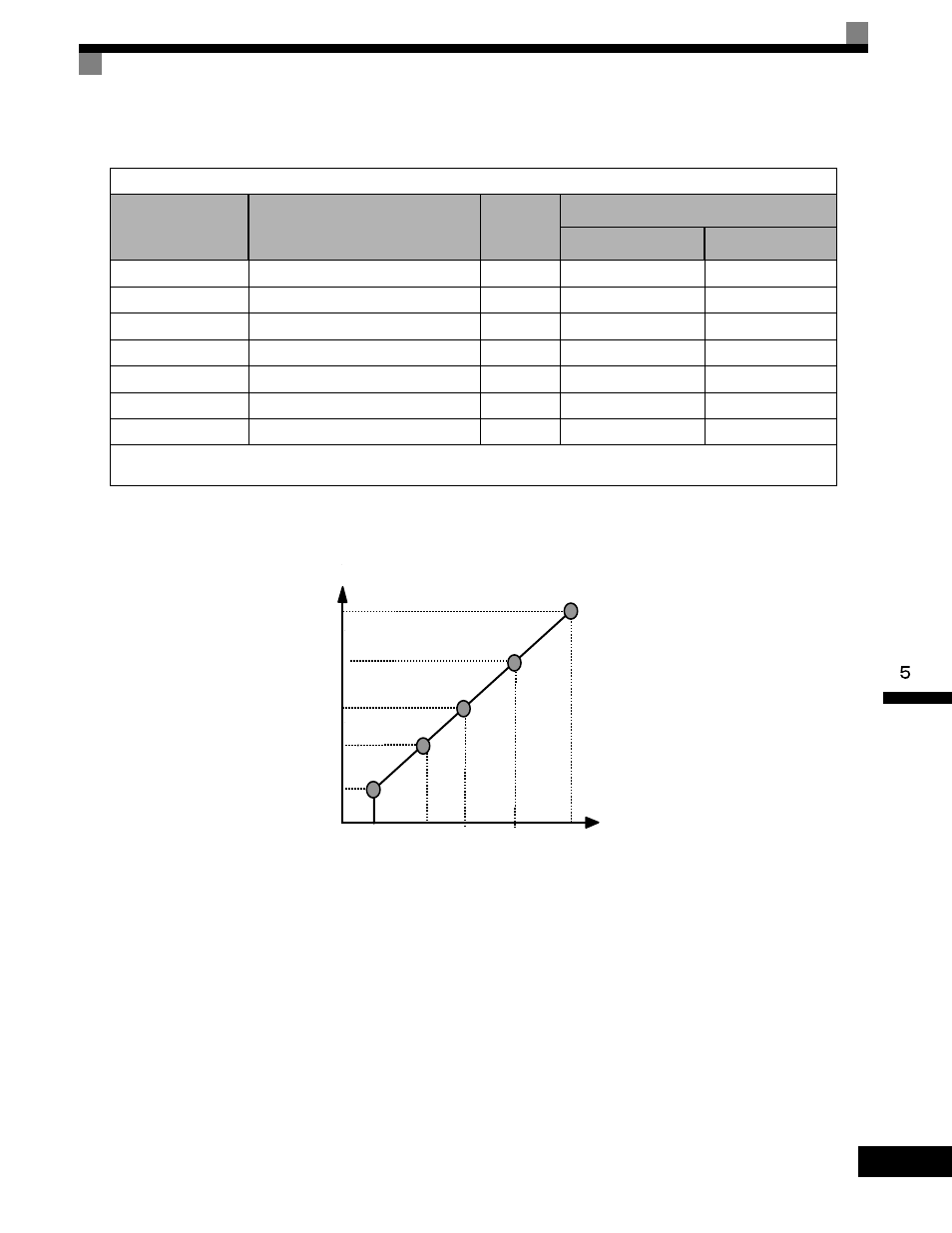
Fig 5.9 V/F Pattern Parameters
Parameters E1-07, E1-08, E1-10, E1-11, and E1-12 are accessible through the Programming Menu.
To set up a custom V/F pattern, program the points shown in the diagram below using parameters E1-04 through
E1-13. Be sure that the following condition is true: E1-09
≤ Ε1−07 < Ε1−06 ≤ Ε1−11 ≤ Ε1−04
Table 5.6 V/F Pattern for 208-240V Class Drives
Parameter No.
Name
Unit
Factory Setting
Open Loop Vector
Flux Vector
E1-04
Max. Output Frequency
Hz
60.0
60.0
E1-05
Max. Output Voltage
V
230.0
230.0
E1-06
Base Frequency
Hz
60.0
60.0
E1-07
Mid. Output Frequency
V
3.0
0.0
E1-08
Mid. Output Voltage
V
12.6
0.0
E1-09
Min. Output Frequency
Hz
0.5
0.0
E1-10
Min. Output Voltage
V
2.3
0.0
1.
The setting shown are for 208-240Vac Drives. The values will double for 380-480Vac Drives.
2. These default values are for open loop vector or flux vector control methods (A1-02 = 2 or 3)
Frequency
Voltage
E1-09 E1-07
E1-06
E1-04
E1-11
Max Voltage E1-05
Mid Voltage B E1-12
Mid Voltage A E1-08
Base Voltage E1-13
Min Voltage E1-10
Min
Freq
Max
Freq
Base
Freq
Mid
Freq
A
Mid
Freq B
Mid
Freq A