Wiring control circuit terminals, Wire sizes and closed-loop connectors, Wiring control circuit terminals -22 – Yaskawa G7 Drive User Manual
Page 53: Wire sizes and closed-loop connectors -22
2
-22
Wiring Control Circuit Terminals
Wire Sizes and Closed-loop Connectors
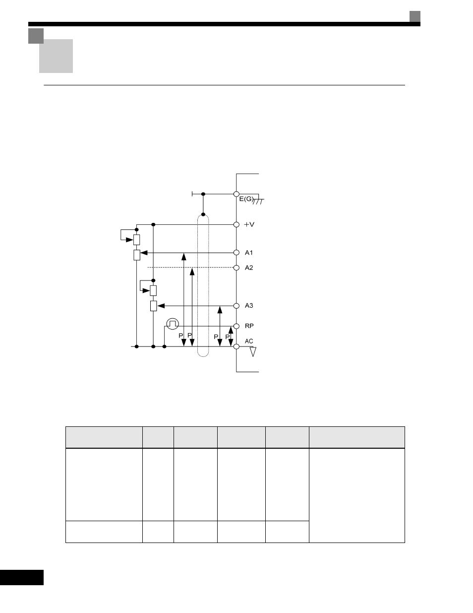
For remote operation using analog signals, keep the control line length between the Digital Operator or
operation signals and the Drive to 50 m (164 ft) or less, and separate the lines from high-power lines (main
circuits or relay sequence circuits) to reduce induction from peripheral devices.
When setting frequencies from an external frequency reference (and not from a Digital Operator), used
shielded twisted-pair wires and ground the shield to terminal E (G), as shown in the following diagram.
Fig 2.13
Terminal numbers and wire sizes are shown in Table 2.9.
* 1. Use shielded twisted-pair cables to input an external frequency reference.
* 2. Yaskawa recommends using straight solderless terminals on digital inputs to simplify wiring and improve reliability.
* 3. Yaskawa recommends using a thin-slot screwdriver with a 3.5 mm blade width.
Table 2.9 Terminal Numbers and Wire Sizes (Same for all Models)
Terminals
Terminal
Screws
Tightening
Torque
lb-in (N•m)
Possible Wire
Sizes
AWG (mm
2
)
Recommended
Wire Size AWG
(mm
2
)
Wire Type
FM, AC, AM, M3, M4,
SC, A1, A2, A3, +V, -V,
S1, S2, S3, S4, S5, S6,
S7, S8, MA, MB, MC,
M1, M2, P3, C3, P4, C4,
MP, RP, R+, R-, S9, S10,
S11, S12, S+, S-, IG, SN,
SP
Phoenix
type
*3
4.2 to 5.3
(0.5 to 0.6)
Stranded wire:
26 to 16
(0.14 to 1.5)
18
(0.75)
•Shielded, twisted-pair wire
*1
•Shielded, polyethylene-
covered, vinyl sheath cable
*2
E (G)
M3.5
7.0 to 8.8
(0.8 to 1.0)
20 to 14
(0.5 to 2)
12
(1.25)
Speed setting power supply, +15 V 20 mA
Master speed reference, -10 to 10 V
Master speed reference, 4 to 20 mA
Pulse input, 32 kHz max.
Auxiliary reference
Analog common
2 k
Ω
2 k
Ω
2 k
Ω
2 k
Ω
Shield terminal