Yaskawa J7 Drive User Manual
Page 9
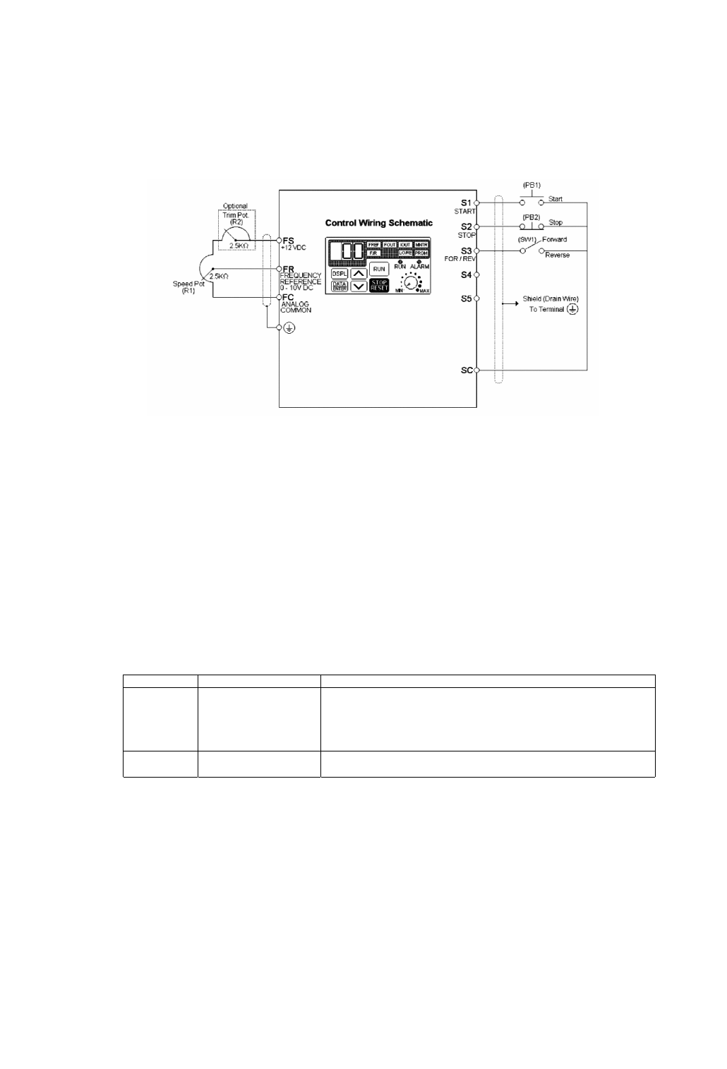
Example 3: Remote Sequence (3-Wire) & Speed Potentiometer
This configuration is best when a person rather than an external controller (PLC, relay, etc.) controls the
D
rive.
Both potentiometers ((R1) & (R2)) should have a resistance value between 2000
Ω and 3000Ω and be rated for
at least 1 Watt. The trim pot is optional, but without it the manual speed pot will output 10V (60 Hz) at just
three-quarters of its rotation.
OPERATION:
• Close pushbutton (PB1) momentarily while pushbutton (PB2) is closed and the drive will start.
Pushbutton (PB1) does NOT need to be maintained.
• Open pushbutton (PB2) at any time and the drive will stop.
• If switch (SW1) is open the drive will run in the forward direction. If switch (SW1) is closed, the drive will
run in the reverse direction. Switch (SW1) can be operated with the drive running at any speed.
• Frequency reference is proportional to the signal level at Terminal FV.
0V = 0 Hz, 5V = 30 Hz, & 10V = 60 Hz.
• If the drive is put in the “Local” mode using the LO/RE quick start LED, the drive will behave the same as
illustrated in Example 1.
Table 4: Programming Required For Remote 3-wire Sequence & Speed Pot Reference
Parameter Display
Description
n01
11
The drive will perform a 3-wire reset.
CAUTION: Setting this value will reset all parameters to their
original factory settings (all previous adjustments will be lost)
When the drive completes the reset, this parameter returns to a
value of 1.
n32 Set
Motor
FLA
Enter the motor’s full load amps (as shown on the motor
nameplate).
After the programming is complete, the trim pot needs to be calibrated. Press DSPL until the FREF quick start
LED is illuminated. Turn the Speed Pot (R1) all the way up. Adjust the trim pot (R2) so that the “FREF”
display is just flickering between 59.9 Hz and 60.0 Hz. This completes the trim pot calibration.
- vii -