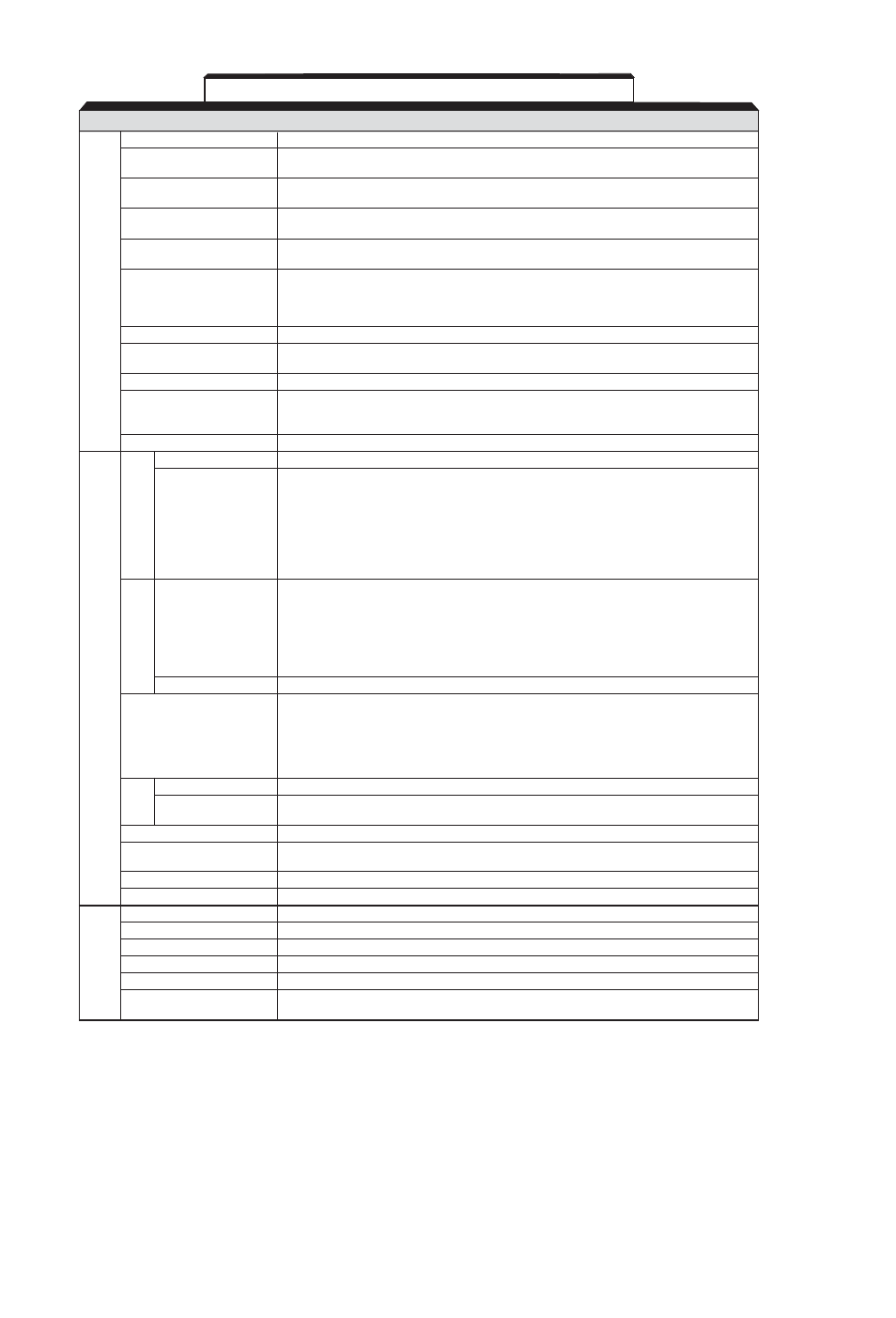
A2-2, Table a2-1. standard specifications (continued) – Yaskawa J7 Drive User Manual
Page 87
A2-2
NOTES:
(1)
Based on an N.E.C. standard 4-pole motor for max. applicable motor output.
(2)
Shows deceleration torque for an uncoupled motor decelerating from 60 Hz in 0.1 seconds.
(3)
Contact your Yaskawa representative for wiring distances greater than 328 ft. (100 m).
(4)
Temperature during shipping (for short periods of time).
SECTION B. All Models (Continued)
Motor overload protection
Electronic thermal overload protection
Motor coasts to stop at approx. 200%
Instantaneous overcurrent
of drive current
Motor coasts to stop after 1 min. at 150% of
Overload
drive rated current
Motor coasts to stop if DC bus voltage exceeds
Overvoltage
410VDC (230V), 820VDC (460V)
Motor coasts to stop when DC bus voltage is
Undervoltage
210VDC or less (230V), 400VDC or less (460V)
The following operations are selectable:
Momentary Power Loss
• Not provided (stops if power loss is 15 ms or longer)
• Automatic restart at recovery from 0.5 sec. power loss
• Automatic restart
Heatsink overheat
Protected by electronic circuit
Independently programmable during accel and
Stall prevention level
constant-speed running. Selectable during decel.
Ground fault
Protected by electronic circuit (overcurrent level)
ON until the DC bus voltage becomes 50V or less.
Power charge indication
RUN lamp says ON or digital operator LED stays ON.
(Charge LED is Provided for 400V)
Cooling Fan Fault
Protected by electronic circuit
Run/stop input
2-Wire or 3-Wire
Seven of the following input signals are selectable:
Forward/reverse run (3-Wire sequence), fault reset,
external fault (NO/NC contact input), multi-step speed operation,
Multi-function input
Jog command, accel/decel time select,
external baseblock (NO/NC contact input, speed search command,
accel/decel hold command, LOCAL/REMOTE selection,
communication/control circuit terminal selection,
emergency stop fault emergency stop alarm
Following output signals are selectable
(1 NO/NC contact output):
Fault, running, zero speed, at frequency, frequency detection
Multi-function output
(output frequency ≤ or ≥ set value), during overtorque detection,
during undervoltage detection, minor error, during baseblock, operation mode,
inverter run ready, during fault retry, during UV, during speed search,
data output through communication
Analog monitor
0 to +10VDC output, programmable for output frequency or output current
Full-range automatic torque boost, auto restart,
upper/lower frequency limit, DC injection braking current/time at start/stop,
Standard functions
frequency reference gain/bias, prohibited frequencies,
analog meter calibrating gain, S-curve accel/decel, slip compensation,
MODBUS communications optional (RS232 or RS485/422, Max. 19.2K bps),
frequency reference from digital operator pot
Status indicator LEDs
RUN and ALARM LEDs provided as standard
Digital Operator
Monitors frequency reference, output frequency,
output current, FWD/REF selection
Terminals
Screw terminals for both main circuit and control circuit
Wiring distance between
drive and motor
328 ft (100 m) or less
(3)
Enclosure
Protected chassis (IP 20)
Cooling method
Self-cooling/cooling fan
Ambient temperature
14 to 122°F (-10 to 50°C)
Humidity
95% RH or less (non-condensing)
Storage temperature
(4)
-4 to 140°F (-20 to 60°C)
Location
Indoor (free from corrosive gases or dust)
Elevation
3,280 feet (1,000 m), higher altitudes by derate
Vibration
Up to 1G, at less than 20 Hz;
up to 0.2G, at 20 to 50 Hz
Table A2-1. Standard Specifications (Continued)
Protective Functions
Environmental
conditions
Other Functions
Input signals
Output signals
Display