5 carrier frequency, Carrier frequency -5 – Yaskawa J7 Drive User Manual
Page 40
5-5
n46
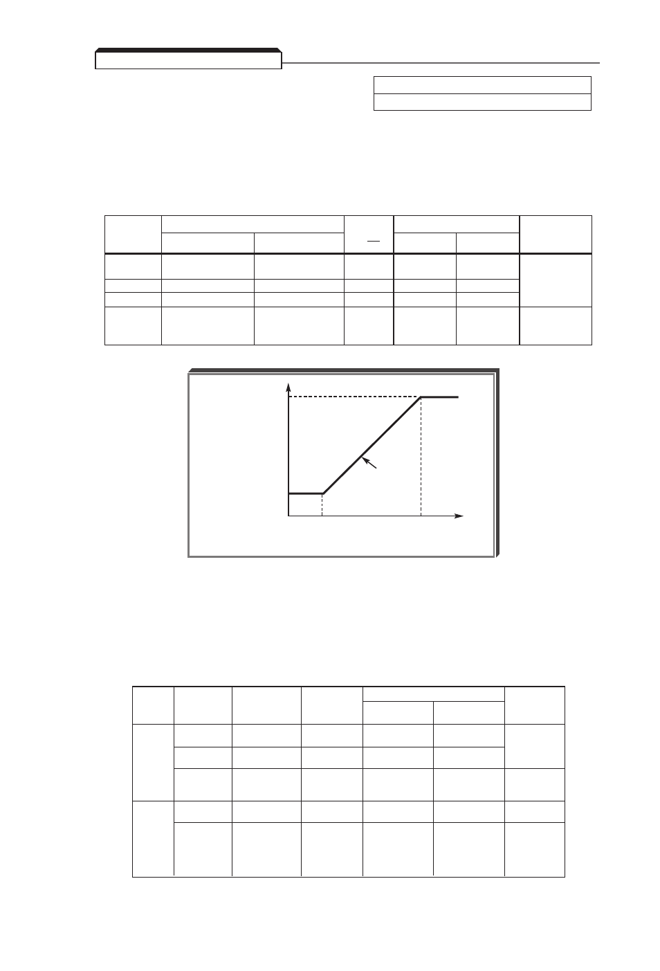
CARRIER FREQUENCY(kHz)
SLOPE
OUTPUT FREQUENCY(Hz)
MODE
SETTING
Maximum(Fc
MAX
)
Minimum(Fc
MIN
)
(=Fc)
Fo
F1
F2
1
2.5
2.5
0
NA
NA
CONSTANT
2
5.0
5.0
0
NA
NA
3
7.5
7.5
0
NA
NA
4
10.0
10.0
0
NA
NA
7
2.5
1.0
12
83.3
208.3
SYNCHRONOUS
8
2.5
1.0
24
41.6
104.1
9
2.5
1.0
36
27.7
69.4
n46 :
Carrier Frequency Upper Limit
Factory Setting:
3 or 4 (see table below)
Range: 1 to 4; 7 to 9
The relationship between output frequency and carrier frequency is determined from the set value
of
n46
.
(a) For constant carrier frequency, set to " 1 ", " 2 ", " 3 ", " 4 ".
(b) For synchronous mode, set
n46
to " 7 ", " 8 ", or " 9 ". These setting values
establish carrier frequencies of 12f, 24f, or 36f, respectively.
Fc
MAX
CARRIER
FREQUENCY
SLOPE
Fc
MIN
0
F1
F2
OUTPUT FREQUENCY
5.5 CARRIER FREQUENCY
Carrier frequency should be decreased as the distance between the Drive and the motor increases,
to reduce capacitive coupling in the motor leads.
• For wiring distances greater than 100m (328 ft.),
n46
should be set to 2.5 kHz (data " 1 " )
or less.
Setting carrier frequency to a value higher than its factory setting requires derating of the drive’s
output current - refer to the following table:
Rated
Input
Old Drive
Model No.
New Drive
Model No.
CIMR-J7AM
Rated
Output
Current (A)
n46
Derated
Output
Current (A)
(1)
Factory
Setting
Frequency
(kHz)
JDA001
JDA002
JDA003
JDA005
JDA008
JDA011
JDA017
JDB001
JDB002
JDB003
JDB005
–
–
JDB009
20P10
20P20
20P40
20P70
21P50
22P20
23P70
40P20
40P40
40P70
41P50
42P20
43P00
43P70
0.8
1.6
3.0
5.0
8.0
11.0
17.5
1.2
1.8
3.4
4.8
5.5
7.2
8.6
4
4
4
4
3
3
3
3
3
3
3
3
3
3
10
10
10
10
7.5
7.5
7.5
7.5
7.5
7.5
7.5
7.5
7.5
7.5
No
Derate
Required
7.0
10.0
16.5
1.0
1.6
3.0
4.0
4.8
6.3
7.6
230V
460V
(1) Derated Output Current values are the maximum currents available with a
carrier frequency
n46
setting of “4” (10kHz).