4 electrical installation, Electrical installation -4 – Yaskawa J7 Drive User Manual
Page 16
1-4
The Drive leaves the factory with all parameters set for 2-Wire external reference control. Figure 1-5
must be used for all external connections.
To use the Drive in a 3-Wire application, Drive parameters n01, n02, and n03 must be
reprogrammed, using the Digital Operator. Figure 1-6 must then be used for all external connections.
A. Main Circuit Input/Output
Complete wire interconnections according to Tables 1-1 and 1-2; observe the following:
• Use 600 V vinyl-sheathed wire (75°C copper) or equivalent. Wire size should be determined
considering voltage drop of leads.
• NEVER connect AC main power to output terminals T1 ( U ), T2 ( V ), and T3 ( W ).
• NEVER allow wire leads to contact metal surfaces. Short-circuit may result.
• NEVER connect power factor correction capacitors or noise filters to Drive output.
• SIZE OF WIRE MUST BE SUITABLE FOR CLASS I CIRCUITS.
• Use only factory supplied installation instructions to install optional dynamic braking resistors.
Failure to do so may cause equipment damage or personal injury.
• Motor lead length should NOT EXCEED 164 feet (50 meters), and motor wiring should be run in
a separate conduit from the power wiring. If lead length must exceed this distance, reduce
carrier frequency and consult factory for proper installation procedures.
• Use UL listed closed loop connectors or CSA certified ring connectors sized for the selected wire
gauge. Install using the correct crimp tool recommended by the connector manufacturer.
1.4 ELECTRICAL INSTALLATION
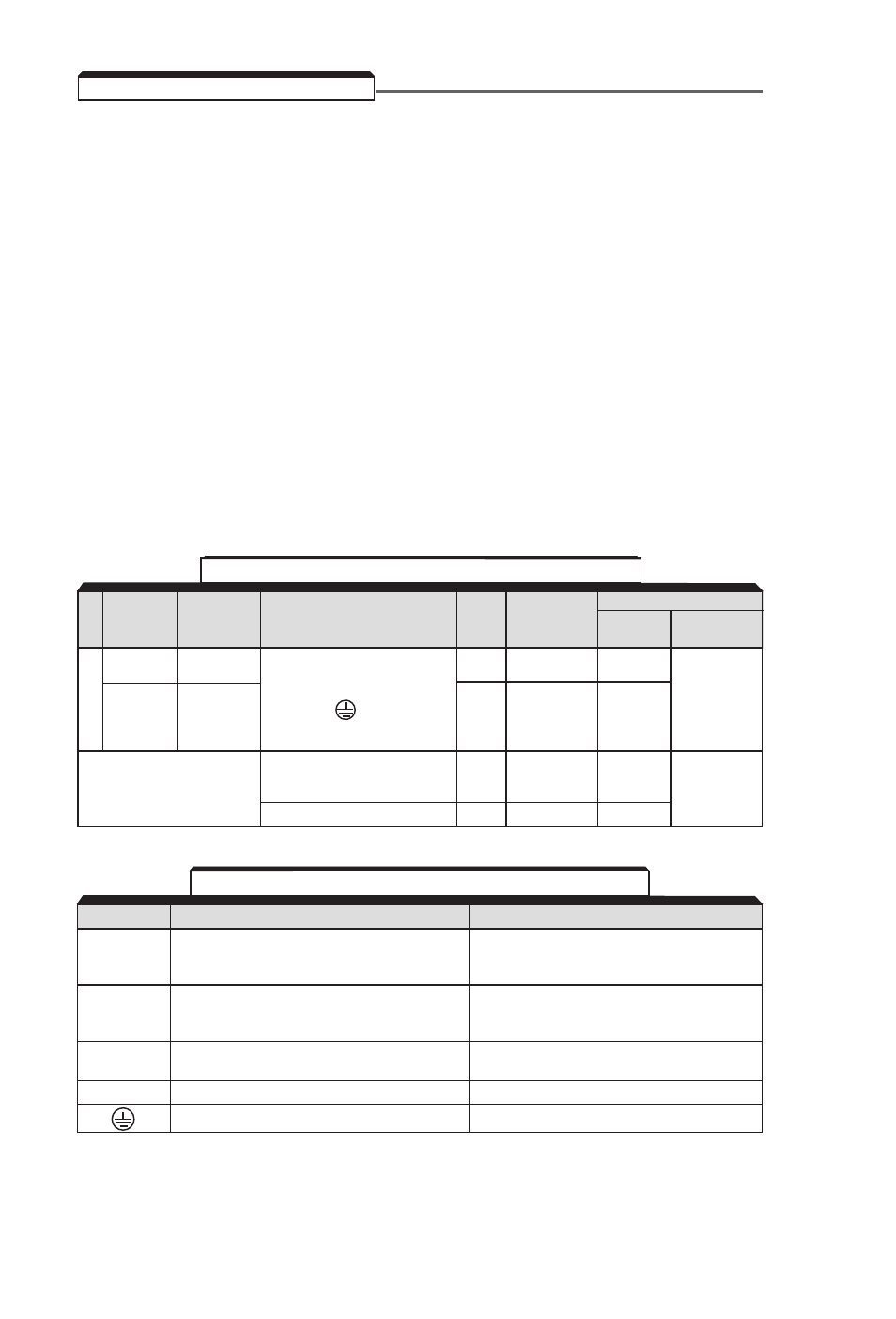
Table 1-1. Wire and Terminal Screw Sizes
Old Drive
New Drive
Terminal Symbol
Screw Max. Torque
Wire
Model No.
Model No.
lb-ft
Size AWG
Type
CIMR-J7AM
JDA001-
20P10-
M3.5
0.7
18 to 14
JDA005
20P70
JDA008-
21P50-
L1, L2, L3, B1, B2, –, +1, +2
JDA017;
23P70;
T1, T2, T3,
M4
1.1
14 to 10
600V
JDB001-
40P20-
JDB009
43P70
Control
S1–S5, SC, FS, FR,
Circuit
FC, AM, AC,
M2
0.2
20 to 16
Shielded wire
(All)
with Class 1
MA, MB, MC
M3
0.4
20 to 16
wiring
TERMINAL
FUNCTION
VOLTAGE / SIGNAL LEVEL
L1 (R)
L2 (S)
Main circuit input power supply
230V Drive: 200 / 208 / 220 / 230V at 50/60 Hz
L3 (T)
460V Drive: 420 / 440 / 460 / 480V at 50/60 Hz
T1 (U)
T2 (V)
Main circuit output
230V Drive: 0 - 200 / 208 / 220 / 230V
T3 (W)
460V Drive: 0 - 400 / 440 / 460 / 480V
+1
DC Reactor terminals
+2
–
DC Bus terminals (+1 & –)
Ground terminal (100 ohms or less)
– – – –
Table 1-2. Main Circuit Terminal Functions and Voltages
Main Circuit