Appendix 2. specifications, Appendix 2, Specifications – Yaskawa J7 Drive User Manual
Page 86: A2-1, Table a2-1. standard specifications
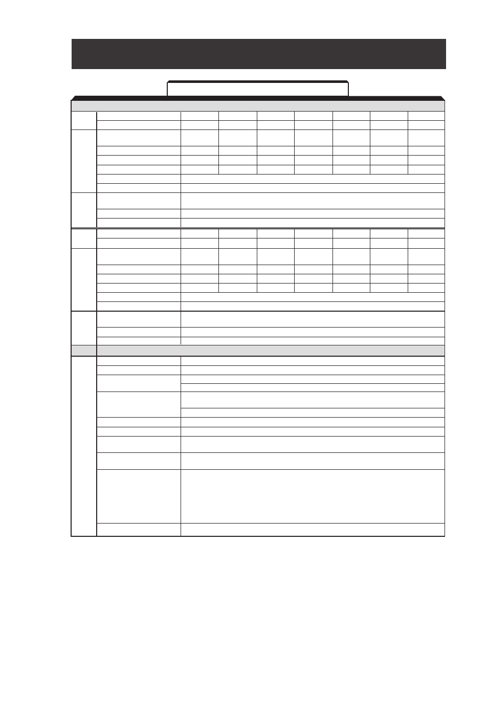
A2-1
(table continued on next page)
Appendix 2. SPECIFICATIONS
See notes at end of table.
SECTION A. Model No. Related Specifications
Old Model No.
JDA001
JDA002
JDA003
JDA005
JDA008
JDA011
JDA017
New Model No. CIMR-J7AM
20P10
20P20
20P40
20P70
21P50
22P20
23P70
Max. applicable motor output
1/8
1/4
1/2
1
2
3
5
HP
(1)
Drive capacity (kVA)
0.3
0.6
1.1
1.9
3.0
4.2
6.7
Rated Output Current (A)
0.8
1.6
3.0
5.0
8.0
11.0
17.5
Rated Input Current (A)
1.1
1.8
3.9
6.4
11.0
15.1
24.0
Max. Output Voltage (V)
200V to 230V (proportional to input voltage)
Max. Output Frequency (Hz)
400 Hz (programmable)
Rated Input Voltage and
three-phase. 200 to 230 V, 50/60 Hz
Frequency
Allowable voltage fluctuation
-15% to +10%
Allowable frequency fluctuation
±5%
Old Model No.
JDB001
JDB002
JDB003
JDB005
--
--
JDB009
New Model No. CIMR-J7AM
40P20
40P40
40P70
41P50
42P20
43P00
43P70
Max. applicable motor
output HP
(1)
1/2
3/4
2
3
3
3
5
Drive capacity (kVA)
0.9
1.4
2.6
3.7
4.2
5.5
7
Rated Output Current (A)
1.2
1.8
3.4
4.8
5.5
7.2
8.6
Rated Input Current (A)
1.6
2.4
4.7
7.0
8.1
10.3
12.0
Max. Output Voltage (V)
380 to 460V (proportional to input voltage)
Max. Output Frequency (Hz)
400 Hz (programmable)
Rated Input Voltage and
three-phase. 380 to 460 V, 50/60 Hz
Frequency
Allowable voltage fluctuation
-15% to +10%
Allowable frequency fluctuation
±5%
SECTION B. All Models
Control method
Sine wave PWM (V/f Control)
Frequency control range
0.1 to 400 Hz
Frequency accuracy
Digital command: ±0.01% (14 to 122°F, -10 to +50°C)
(temperature change)
Analog command: ±0.5% (77°F ± 18°F, 25°C ± 10°C)
Digital Operator reference: 0.1 Hz (< 100Hz)
Frequency setting resolution
1 Hz (100Hz or more)
Analog reference: 0.06Hz/60Hz (1/1000)
Output frequency resolution
0.01 Hz
Overload capacity
150% of rated output current for 1 minute
0 to 10VDC (20kΩ), 4 to 20mA (250Ω), 0 to 20mA (250Ω) pulse train input,
Frequency Reference Signal
Digital Operator Pot
0.01 to 6000 sec.
Accel/Decel Time
(accel/decel time are independently programmed)
Short-term average deceleration torque (2)
0.2kW: 150%
0.75kW: 100%
Braking Torque
1.5kW: 50%
2.2kW or more: 20%
Continuous regenerative torque: Approx. 20%
V/f characteristics
Custom V/f pattern
Table A2-1. Standard Specifications
Output
Char
acter
istics
Po
w
er
Supply
Output
Char
acter
istics
Control Char
acter
istics
Po
w
er
Supply
230 VAC
3-Phase
460 VAC
3-Phase