Yaskawa J7 Drive User Manual
Page 84
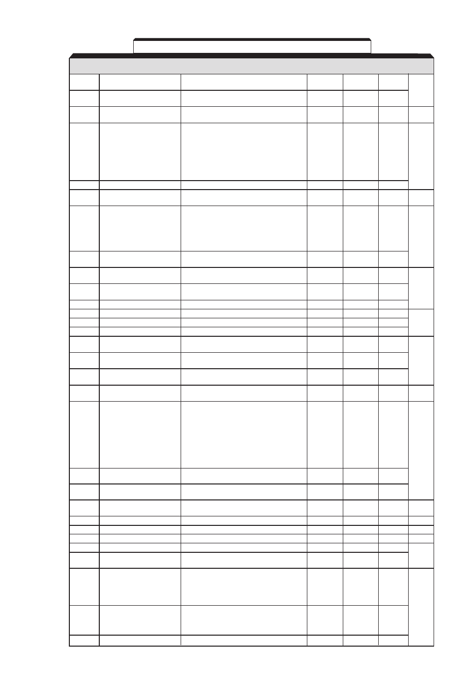
PARAM-
SETTING RANGE
SETTING
FACTORY
USER
PARA.
ETER
NAME
(AND UNITS)
INCREMENT
SETTING
SETTING
REF.
n41
Analog Frequency Reference
0 to 255
1 (%)
100
Gain
5.8
n42
Analog Frequency Reference
-100 to 100
1 (%)
0
Bias
n43
Analog frequency reference
0.00 to 2.00
0.01 (sec)
0.10
filter time constant
0: Output frequency
1: Output Current
2: DC Bus Voltage
n44
Multi-function Analog Output
(10V / 400 VDC [800 VDC])
(Terminals AM & AC)
3: Motor Torque
1
0
5.16
(10V / Motor rated torque)
4: Output Power
(10V / Drive Capacity kW)
n45
Analog Monitor Gain
0.00 to 2.00
0.01
1.00
n46
Carrier Frequency
1 to 4 (x 2.5 kHz)
1
4
5.5
7 to 9 (synchronous)
0: Not Provided
1: Continuous operation after power
n47
Momentary Power Loss
recovery within 2 sec.
Ride-through Method
2: Continuous operation after power
1
0
5.15
recovery within control logic time
(no fault output)
n48
Number of auto restarts
0 to 10
1
0
attempts
n49
Prohibit Frequency 1
0.00 to 400.0
0.01 (Hz)
0.00
or 0.1 (Hz)
n50
Prohibit Frequency 2
0.00 to 400.0
0.01 (Hz)
0.00
5.6
or 0.1 (Hz)
n51
Prohibit Frequency Deadband 0.0 to 25.5
0.01 (Hz)
0.00
n52
DC Injection Current
0 to 100
1 (%)
50
n53
DC Injection Time at stop
0.0 to 25.5
0.1 (sec)
0.0
5.7
n54
DC Injection Time at start
0.0 to 25.5
0.1 (sec)
0.0
n55
Stall Prevention During
0: Enabled
1
0
Deceleration
1: Disabled
n56
Stall Prevention During
30 to 200
1 (%)
170
5.22
Acceleration
n57
Stall Prevention Level During
30 to 200
1 (%)
160
Running
n58
Frequency Detection Level
0.00 to 400.0
0.01 (Hz)
0.0
5.18
or 0.1 (Hz)
0: Detection Disabled
1: Detect only at set frequency;
operation continues
2: Detect only at set frequency;
n59
Overtorque Detection (OL3)
coast to stop
1
0
3: Detect during all frequency conditions;
5.19
operation continues
4: Detect during all frequency conditions;
coast to stop
n60
Overtorque Detection
Level (OL3)
30 to 200
1 (%)
160
n61
Overtorque Detection
Delay Time (OL3)
0.1 to 10.0
0.1 (sec)
0.1
n62
Up/Down Hold
0: Disabled
Memory
1: Enabled
1
0
5.10
n63
Torque Compensation Gain
0.0 to 2.5
0.1
1.0
5.25
n64
Motor Rated Slip
0.0 to 20.0
0.1 (Hz)
Note 1
5.21
n65
Motor No-load Current
0 to 99
1 (%)
Note 1
n66
Slip Compensation Gain
0.0 to 2.5
0.1
0.0
n67
Slip Compensation Primary
0.0 to 25.5
0.1 (sec)
2.0
5.21
Delay Time
0: Fault - Coast to stop
1: Fault - Ramp to stop (
n17
)
n68
Modbus Time Out
2: Fault - Ramp to stop (
n19
)
1
0
Detection
3: Alarm - operation continues
4: Disabled
0: 0.1 Hz
5.14
n69
Modbus Frequency
1: 0.01 Hz
Reference Unit
2: 100% / 30000
1
0
3: 0.1 %
n70
Modbus Slave Address
0 to 32
1
0
A1-3
Table A1-1. J7 Parameters - Continued