26 v/f pattern, V/f pattern -36 – Yaskawa J7 Drive User Manual
Page 71
5-36
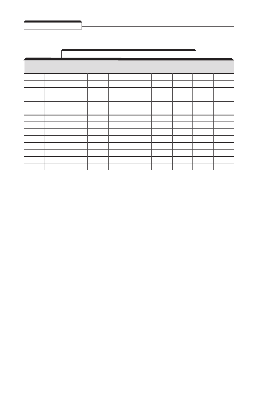
5.26 V/f PATTERN
The V/f pattern can be tailored to suit your specific application and load characteristics by adjusting
parameters
n09
to
n15
(see the V/f characteristics figure on the following page).
NOTES:
1
VT = Variable Torque, typically used for blowers, centrifugal pumps, and fans.
CT = Constant Torque, most other applications. Consult Yaskawa for further assistance.
The following conditions must be considered when selecting a V/f pattern:
- Pattern matches the voltage-frequency characteristics of the motor.
- Maximum motor speed.
2
V/f pattern for high starting torque should be selected for:
- Long wiring distance.
- Large voltage drop at start
- AC reactor connected to Drive input or output.
- Use of motor rated below Drive max. output.
3
Voltages shown are for 230V motors; for other motor voltages, multiply all voltage (V) values by (Vmtr/230).
i.e., for a 460V motor, multiply by 460/230 = 2.
Max.
Starting
Load
n09
n10
n11
n12
n13
n14
n15
Freq.
Torque
Type
1
(Hz)
(V)
3
(Hz)
(Hz)
(V)
3
(Hz)
(V)
3
50
Normal
VT
50.0
230
50.0
25.0
40
1.3
9
50
High
2
VT
50.0
230
50.0
25.0
57
1.3
12
60
Normal
VT
60.0
230
60.0
30.0
40
1.5
9
60
High
2
VT
60.0
230
60.0
30.0
57
1.5
12
50
Normal
CT
50.0
230
50.0
3.0
17
1.5
12
50
Medium
CT
50.0
230
50.0
2.5
23
1.3
13
50
High
2
CT
50.0
230
50.0
2.5
28
1.3
16
60
Normal
CT
60.0
230
60.0
1.5
12
1.5
12
60
Medium
CT
60.0
230
60.0
3.0
20
1.5
13
60
High
2
CT
60.0
230
60.0
3.0
28
1.5
23
72
Normal
CT
72.0
230
60.0
3.0
17
1.5
12
90
Normal
CT
90.0
230
60.0
3.0
17
1.5
12
120
Normal
CT
120
230
60.0
3.0
17
1.5
12
180
Normal
CT
180
230
60.0
3.0
17
1.5
12
Table 5-4. Recommended V/f Patterns