14 modbus control (optional), Modbus control (optional) -15, S- s+ sg r- r – Yaskawa J7 Drive User Manual
Page 50
5-15
The Drive can perform serial communication by using a programmable controller (PLC), MODBUS
protocol, and by installing an optional RS-232 or RS-485/422 interface card. MODBUS is composed
of one master PLC and 1 to 31 (maximum) slave units (Drives). In serial communication between
the master and slaves, the master always starts transmission and the slaves respond to it.
The master communicates with one slave at a time. Address numbers are assigned to each slave in
advance, and the master specifies an address to communicate with. The slave which receives the
command from the master executes the function, and then responds to the master.
A.
Communication Specifications
• Interface
: RS-485 & RS-422, or RS-232
• Synchronization
:
Asynchronous
• Transmission parameters
:
Baud rate
— Selectable from 2400, 4800,
9600, 19,200 BPS (
n71
)
Data length
— Fixed to 8 bits
Parity
— Parity / no parity, even / odd
selectable (
n72
)
Stop bit
— Fixed to 1 bit
• Protocol
:
MODBUS RTU
• Maximum number to units
to be connected
:
31 units
B.1.
Connecting MODBUS - RS-485/422 Interface Option (Model No. RS-485/J7)
Terminals S+, S-, R+, and R- are used for Modbus communications. A terminating resistor can be
enabled between R+ and R- by setting SW1 to “ON.” SW1 is found on the optional interface, SI-
485/J7, and turns the terminating resistor on and off.
The terminating resistor should only be enabled on the drive farthest away from the master.
B.2.
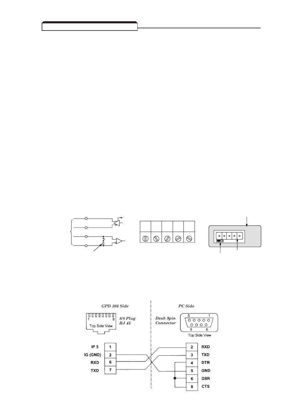
Connecting MODBUS - RS-232 Interface Option (Model No. RS-232/J7)
Cable must be assembled per pin-out diagram shown below.
5.14 MODBUS CONTROL (OPTIONAL)
S+
S–
R+
RS-422A
or RS-485
TERMINAL RESISTOR (1/2W, 120
Ω
)
SW1
R–
S- S+ SG R- R+
CONNECTOR
SW1
FACE PLATE