Yaskawa J7 Drive User Manual
Page 17
1-5
B. Control Circuit
All basic control circuit (signal) interconnections are shown in the appropriate diagram:
• Interconnections for external two-wire control in combination with the Digital Operator are
shown in Figure 1-5 (for 230V or 460V rated drives).
• Interconnections for external three-wire control in combination with the Digital Operator are
shown in Figure 1-6 (for 230V or 460V rated drives).
Make wiring connections according to Figures 1-1 thru 1-6 and Table 1-3, observing the following :
• Signal Leads : Terminals S1-S5 & SC; FS, FR, & FC; and AM & AC.
• Control Leads : Terminals MA, MB & MC.
• Power Leads : Input Terminals L1 (R), L2 (S), and L3 (T), and Output Terminals T1 (U), T2
(V), and T3 (W).
• Use twisted shielded or twisted-pair shielded wire (20-16 AWG (0.5-1.25mm
2
)) for control
and signal circuit leads. Use twisted shielded or twisted-pair shielded wire (20-14 AWG
(0.5-2mm
2
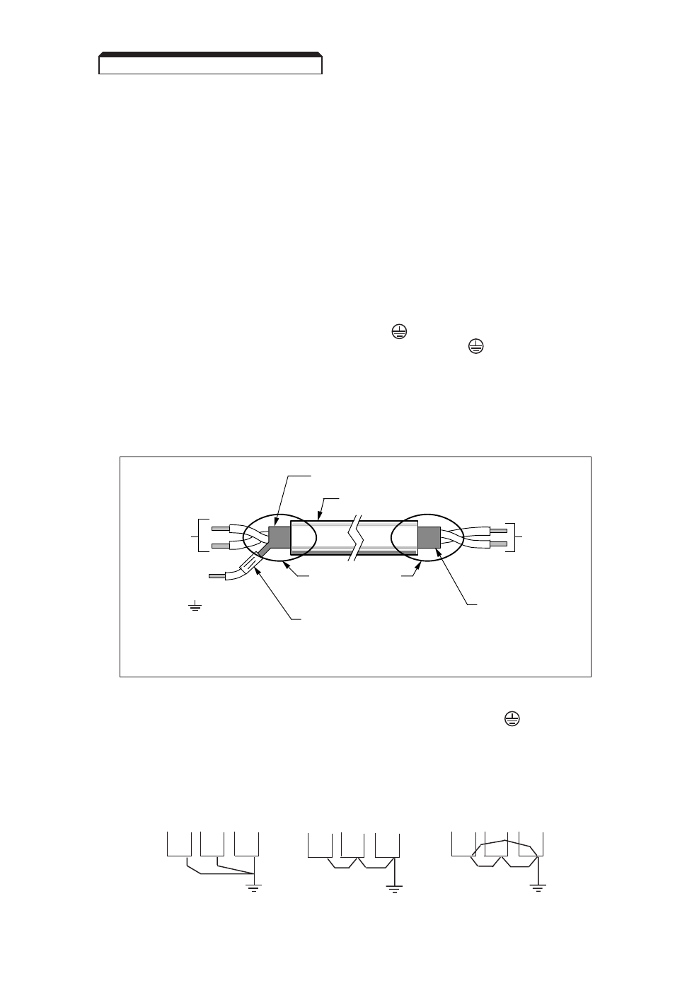
)) for shield sheath terminal (terminal ). When using shielded wire, the
shield sheath MUST be connected at the Drive ONLY (terminal ). The other end
should be dressed neatly and left unconnected (floating). See Figure 1-2.
• Signal leads (see above) must be separated from control leads, main circuit leads L1 (R),
L2 (S), L3 (T), T1 (U), T2 (V), T3 (W), and any other power cables, to prevent erroneous
operation caused by noise interference.
• Lead length should NOT EXCEED 164 feet (50 meters). Wire sizes should be determined
considering the voltage drop.
TO GPD 305
SIGNAL
TERMINALS
TO SHIELD
SHEATH
TERMINAL
(TERM. )
WRAP BOTH ENDS
OF SHEATH WITH
INSULATING TAPE
CRIMP
CONNECTION
SHIELD SHEATH
OUTER JACKET
DO NOT
CONNECT
TO
EXTERNAL
CIRCUIT
Figure 1-2. Shielded Sheath Termination
Continued
1.4 ELECTRICAL INSTALLATION
•
•
•
•
•
•
•
•
•
•
CORRECT
CORRECT
NOT
ACCEPTABLE
C. Grounding
• The Drive must be solidly grounded using main circuit ground terminal .
Ground resistance should be 100 ohms or less. Select lead size suitable for size
of terminal screw. Make the length as short as possible.
• NEVER ground the Drive in common with welding machines, motors, or
other large-current electrical equipment.
• Where several Drives are used, ground each directly or daisy-chain to the
ground pole(s). DO NOT FORM A LOOP WITH THE GROUND LEADS.