6 - fault diagnosis and corrective actions, 1 general, Fault diagnosis and corrective actions – Yaskawa J7 Drive User Manual
Page 74: General -1
6-1
This section describes the alarm and fault displays, explanations for fault conditions and corrective
actions to be taken if the Drive malfunctions.
A failure in the Drive can fall into one of two categories, Alarm or Fault.
A blinking “Alarm” indication is a warning that a trouble condition will soon occur, or that a
programming error has been made. The Drive will continue to operate during an “Alarm” indication.
A blinking “Minor Fault” indication is displayed during less serious faults, or when a problem exists in
the external circuitry. The Drive will continue to operate, and a “Minor Fault” contact will be closed if a
multi-function output is programmed for the condition.
A steady “Major Fault” indication is displayed when the Fault relay has tripped. The motor coasts to a
stop, and a fault signal output is present at control circuit terminals MA, MB and MC.
Section 6. FAULT DIAGNOSIS AND CORRECTIVE ACTIONS
6.1 GENERAL
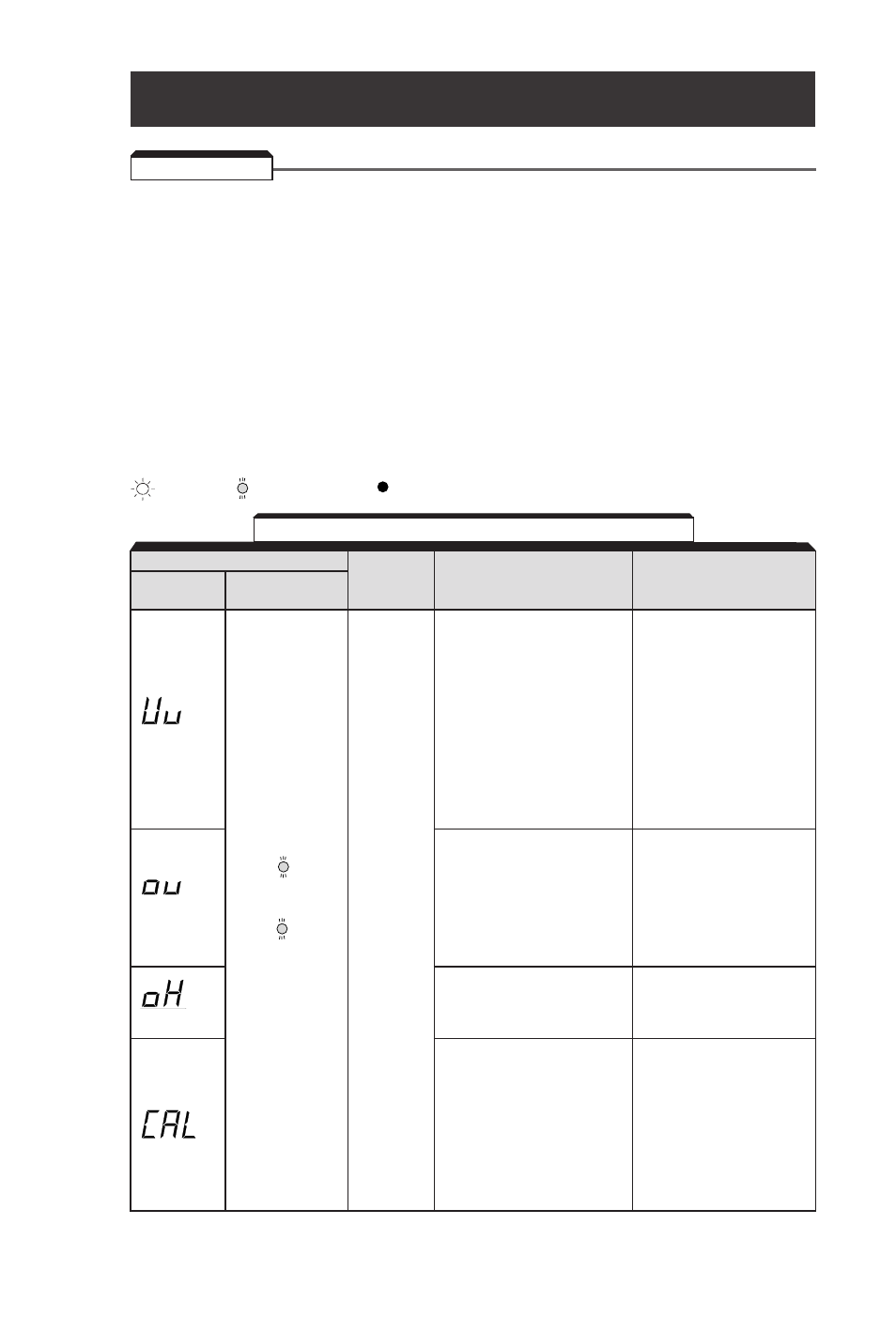
Alarm Display
Digital
RUN (Green)
Drive
Explanation
Causes and
Operator
ALARM (Red)
Status
Corrective Actions
UV (Main circuit low voltage)
Check the following:
Main circuit DC voltage
• Power supply voltage
drops below the low-voltage
• Main circuit power
detection level while the
supply wiring is
drive output is OFF.
connected.
230V: Stops at main circuit
• Terminal screws are
DC voltage below
securely tightened.
Blinking
approx. 200V
(160V for single-
phase)
460V: Stops at main circuit
DC voltage below
approx. 400 V
OV (Main circuit overvoltage)
Check the power supply
Warning
Main circuit DC voltage
voltage.
only.
exceeds the over voltage
Fault
detection level while the
Blinking
contacts
drive output is OFF.
do not
Detection level: approx.
change
410V or more (approx.
state.
820V for 460V class).
OH (Cooling fin overheat)
Check the intake air
Intake air temperature
temperature.
Blinking
rises while the drive
output is OFF.
CAL (MODBUS
Check communication
communications waiting)
devices, and transmission
Correct data has not been
signals.
received from the PLC
when the parameter
n02 (operation command
Blinking
selection) is 2 or
n03 (frequency reference
selection) is 6,
and power is turned ON.
Table 6-1. Alarm Displays and Corrective Actions
: ON
: BLINKING
: OFF