Appendix 1. listing of parameters, A1-1, Table a1-1. j7 parameters – Yaskawa J7 Drive User Manual
Page 82
A1-1
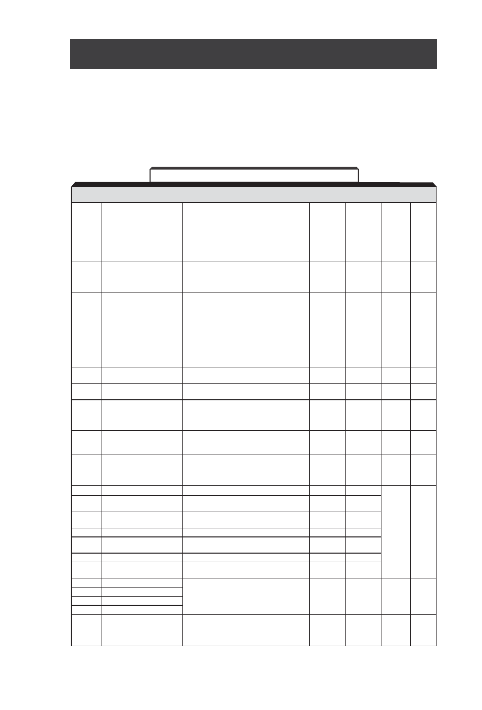
The Drive control circuits use various parameters to select functions and characteristics of the Drive.
Changing of parameter settings must be done in the Program mode, or by use of the Function
LEDs, if available (see Section 4).
The following table lists all parameters in numerical order. For each parameter, reference
paragraph(s) in Section 5 are listed (if applicable) where the features of the Drive affected by that
parameter are described.
Table A1-1. J7 Parameters
Appendix 1. LISTING OF PARAMETERS
PARAM-
SETTING RANGE
SETTING
FACTORY
USER
PARA.
ETER
NAME
(AND UNITS)
INCREMENT
SETTING
SETTING
REF.
0:
n01 can be read and set;
n02 - n79 read only
1:
n01 - n79 can be read and set
2-5: Not Used
1
1
5.20
n01
Parameter Selection /
6:
Clear Fault History Only
Initialization
7:
Not Used
10: 2 wire initialization (USA Spec)
11: 3 wire initialization (USA Spec.)
0:
Digital Operator
n02
Operation Method Selection
1:
Terminal
1
1
5.13
2:
Serial Communication (Modbus)
0:
Digital Operator Pot
1:
Digital Operator
2:
Voltage Reference (0 to 10V)
3:
Current Reference (4 to 20 mA)
n03
Reference Selection
4:
Current Reference (0 to 20 mA)
5:
Serial Communications (Modbus)
1
2
5.13
n04
Stop Method
0:
Ramp to stop
1
0
5.23
1:
Coast to stop
n05
Reverse Prohibit
0:
Reverse Run enabled
1
0
1:
Reverse Run disabled
0:
STOP key is effective regardless of
programming of n02
n06
STOP Key Function
1:
STOP key is effective only when sequence
1
0
5.13
command (per n02) is from Digital Operator
0:
Frequency Reference from digital
n07
Reference Selection -
operator pot
1
0
5.13
Digital Operator
1:
Frequency Reference from n21
0:
ENTER key must be pressed to write-in
n08
Frequency Reference Setting
new value
1
0
5.13
Method From Digital Operator 1:
ENTER key does not have to be pressed
to write-in new value
n09
Frequency - Max.
50.0 to 400.0
0.1 (Hz)
60.0
n10
Voltage - Max.
0.1 to 255.0 (230V drive)
0.1 (V)
230
0.2 to 510.0 (460V drive)
460
n11
Frequency - Max.
0.2 to 400.0
0.1 (Hz)
60.0
Voltage Point
n12
Frequency - Midpoint
0.1 to 399.9
0.1 (Hz)
1.5
5.26
n13
Voltage - Midpoint
0.1 to 255.0 (230V drive)
0.1 (V)
12
0.2 to 510.0 (460V drive)
n14
Frequency - Min.
0.1 to 10.0
0.1 (Hz)
1.5
n15
Voltage - Min.
0.1 to 50.0 (230V drive)
0.1 (V)
12
0.2 to 100.0 (460V drive)
n16
Acceleration Time 1
0.1 (sec)
10.0
n17
Deceleration Time 1
(<100 sec.)
5.2
n18
Acceleration Time 2
0.0 to 999
1 (sec)
n19
Deceleration Time 2
(
≥
100 sec.)
0:
No S-curve
n20
S-curve Selection
1:
0.2 second
1
0
5.3
2:
0.5 second
3:
1.0 second