D view, Siehe „3-d view” auf seite 493), 3 v iews – HEIDENHAIN SW 54843x-03 User Manual
Page 493
HEIDENHAIN MANUALplus 620
493
6.3 V
iews
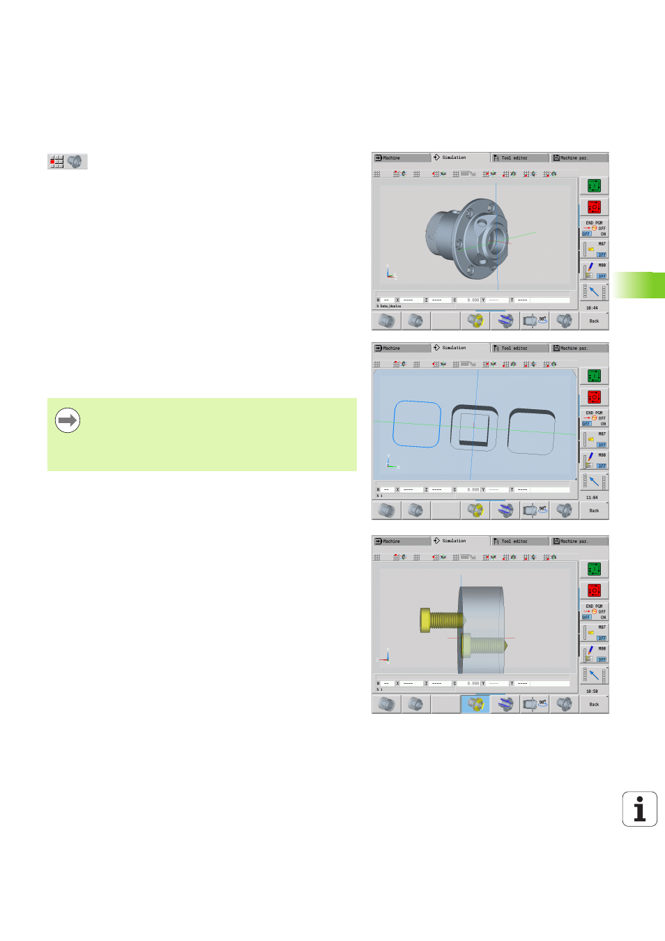
3-D view
The 3-D view menu item switches to a perspective
view and shows the programmed finished part.
With the 3-D view, you can display the blank and the finished part with
all turning operations, milling contours, drilling and boring operations
as well as threads in a solid-model view. Tilted Y planes and machining
operations referenced to them, such as pockets or patterns, are also
displayed correctly by the MANUALplus.
The MANUALplus depicts milling contours depending on the
parameter HC: Milling/drilling attribute defined in G308. If you
have selected the "contour milling," "pocket milling" or "area milling"
values in this parameter, the graphic shows the respective 3-D
elements. If other values are specified in the HC parameter or if values
are missing, the control depicts the described milling contour as a blue
line.
Elements that cannot be calculated by the MANUALplus are displayed
as an orange line; for example, if an open milling contour is
programmed as a pocket.
With the soft keys and the menu functions you can influence the
display of the workpiece.
Check mode
The check mode enables you to verify the correct positioning of holes
and milling contours, for example.
In the check mode the MANUALplus displays turning contours in gray,
and drilling and milling contours in yellow. For a better overview, the
control shows all contours as transparent.
The finished part contour programmed in the FINISHED
section is shown in the graphic regardless of the
machining operation in the NC program.
You can cancel the calculation of the 3-D view by pressing
the ESC key or the Cancel soft key.