Icp cutting, longitudinal, 4 t u rn ing cy cles – HEIDENHAIN SW 54843x-03 User Manual
Page 202
202
Cycle programming
4.4 T
u
rn
ing cy
cles
ICP cutting, longitudinal
Select cut, longitudinal/transverse
Select ICP cutting, longitudinal
The cycle machines the area defined by the starting point and the ICP
contour, taking the oversizes into account.
The tool plunges with the maximum possible angle,
leaving material remaining.
The steeper the tool plunges into the material, the
greater the feed rate decrease (max. 50%).
Cycle parameters
X, Z
Starting point
FK
ICP finished part: Name of the contour to be machined
P
Infeed depth: Maximum infeed depth
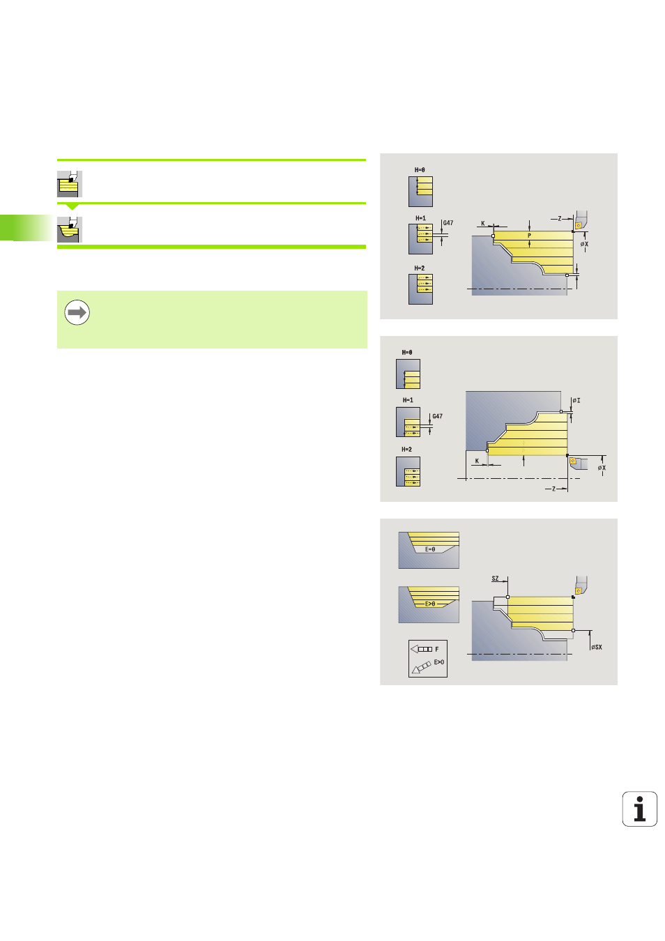
H
Contour smoothing
0: With every cut
1: With the last cut
2: No finishing cut
I, K
Oversize X, Z
E
Plunging behavior:
No input: Automatic feed-rate reduction
E=0: No plunging
E>0: Plunging feed rate in use
SX, SZ
Cutting limits (siehe Seite 142)
G47
Safety clearance (siehe Seite 142)
G14
Tool change point (siehe Seite 142)
T
Turret pocket number
ID
Tool ID number
S
Spindle speed/cutting speed
F
Feed per revolution
BP
Break duration: Time span for interruption of the feed. The
chip is broken by the (intermittent) interruption of the feed.
BF
Break duration: Time interval until the next break. The chip
is broken by the (intermittent) interruption of the feed.
A
Approach angle (reference: Z axis)—(default: parallel
to Z axis)
W
Departure angle (reference: Z axis)—(default:
perpendicular to Z axis)