Connecting an optional footswitch, Connecting the optical edge detector inputs – HEIDENHAIN ND 1300 OED and Crosshair Systems User Manual
Page 27
9
2
Installation
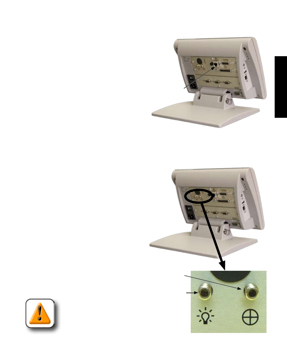
Connecting an optional footswitch
The optional foot switch is connected to the RJ-45 connector
on the rear of the QC-300.
1 Verify that the QC-300 is off.
2 Connect the foot switch to the RJ-45 con-
nector on the rear connector panel.
Connecting the optical edge detector inputs
The optional optical inputs are connected to the two optical jacks on the rear of the QC-300.
1 Connect fiber-optic cables to the QC-300 and then con-
nect to the comparator. The screen sensor cable connector is
marked with a crosshair icon and the reference cable connector
is marked with a light bulb icon. Attach all cables securely to
the appropriate connections.
2 Secure the sensor cable to the comparator screen using the
plastic mounting plate provided. Place the mounting plate
under the comparator’s chart clips so the small hole in
the plate is positioned over a lit portion of the com-
parator screen.
3 Clean the collecting end of the sensor cable with
a soft lint-free cloth as necessary. Place the metal tip of
the sensor cable through the hole in the mounting plate
flush against the screen.
CAUTION
Be careful not to scratch the screen with the metal
tip.
Footswitch connector
Connections
Optical jacks
Reference
cable jack
Sensor
cable jack