Probe path screen – HEIDENHAIN ND 1300 OED and Crosshair Systems User Manual
Page 233
215
10
Setup
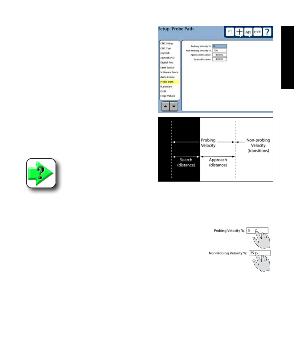
Probe path screen
CNC probing parameters are specified in the Probe
path screen to control CNC probing and non-probing
velocities as well as data point approach and search
distances during program execution.
Probing and non-probing velocities
Transitions from one target edge to the next are made
at relatively high non-probing velocities. When the
approach distance from the edge is reached, the system
velocity is reduced to the slower probing velocity. If
the edge is not recognized at the anticipated point, the
system continues searching at the probing velocity un-
til the end of the specified search distance is reached. If
no edge is recognized within the approach and search
distances, an error message is displayed.
NOTE
In general, the best probing accuracy
is obtained at lower probing veloci-
ties. However, since the system is ac-
curate at higher velocities, the major
velocity consideration is related to the torque required to perform high acceleration and decelera-
tion moves, and the resulting potential for measurement errors.
To specify probing and non-probing velocities:
1 Select the Probing Velocity % field and enter the probing velocity as a
percentage of the maximum CNC velocity.
2 Select the Non-probing Velocity % field and enter the non-probing
velocity as a percentage of the maximum CNC velocity.
Digital Positioner and Probe Path Screens