Connecting axis encoders, Location and mounting, Power surge suppressor – HEIDENHAIN ND 1300 OED and Crosshair Systems User Manual
Page 25
7
2
Installation
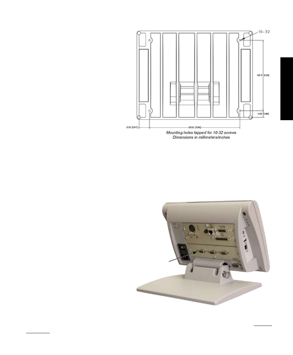
Location and mounting
Rest the QC-300 on a flat, stable surface,
or bolt it to a stable surface from the bot-
tom using four 10/32 screws fastened in
the pattern shown at the right.
Power surge suppressor
Connect the QC-300 to power through a high-quality power surge suppressor. Surge suppressors limit the
amplitude of potentially damaging power line transients caused by electrical machinery or lightning. When
a surge suppressor is not used, power line transients can corrupt system memory or damage circuits.
Connecting axis encoders
Axis encoders are attached to interface connectors on
the rear of the QC-300. Many encoder interfaces are
available to match the wide variety of encoders that
can be used with the QC-300. The type of axis encoder
connectors will vary depending on the application. En-
coder inputs are specified as analog or TTL at the time
of purchase and cannot be changed in
the field.
1 Verify that the QC-300 is off.
2 Connect the axis encoders tightly
to their connectors. An axis label is pro-
vided near each connector. Do not overtighten
the connector screws.
Encoder input parameters must be configured later using the Encoder setup screen. Please refer to Chapter
10: Setup for details regarding encoder setup.
X, Y, Z and Q axis
input connectors
Safety and Power