Super Systems 20PQ User Manual
Page 92
88
Gr. 6
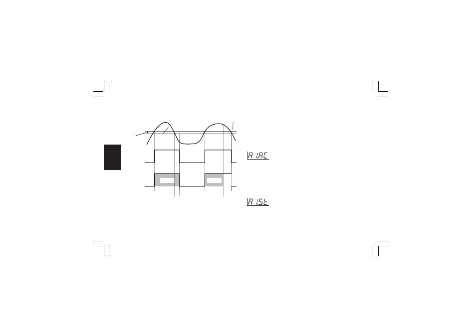
Example for A1.Cn (A2.Cn, A3.Cn) = H.L.
A= alarm condition detection
B= the alarm remains in alarm status (even if the measured
value is under the threshold) until a manual reset is
performed (C).
E= if a manual reset is performed when the alarm condition still
exist; the LED gets steady lit, the alarm remains in the alarm
status until the process variable reaches the alarm threshold
minus hysteresis (D).
NOTE:
The manual reset (acknowledgement) may be performed by the
"ñ.rSt" [R.C01] parameter or by logic input or by serial link.
- Alarm 1 action - [r.F03]
This parameter is available only when OUT 1 is configured as
alarm 1 output (“O1.Fn” [C.E01] = “ALr.1”)
Range: dir
= direct action (Relay energized or SSr=1 in
alarm condition)
rEV
= Reverse action (Relay energized or SSr=1 in
non alarm condition)
- Alarm 1 stand by (mask) function - [r.F04]
This parameter is available only when OUT 1 is configured as
alarm 1 output (“O1.Fn” [C.E01] = “ALr.1”)
Range: OFF = Stand-by function disabled
On
= Stand-by function enabled
A
C
A
E
D
OFF
ON
Relay out
Alarm
Hysteresis
Alarm
Threshold
Measured
Value
OFF
ON
LED 1(2, 3)
B
Flash
Flash
Steady
XKP-1-C2.p65
10/30/01, 9:37 AM
88