Measurement Computing eZ-PostView rev.2.0 User Manual
Page 86
4-8 Edit Menu
969795
eZ-Analyst
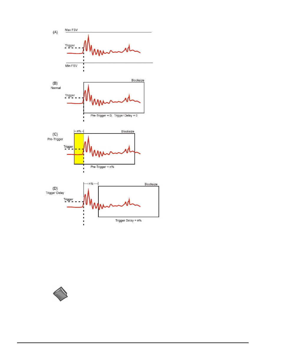
(A) Setting Signal Position
Once an acceptable trigger level has
been ascertained, positioning the
signal within a block of sampled data
(and in the display window) is the
next consideration. Often it is
necessary to capture the events that
lead up to the trigger point. If this is
the situation then positioning should
be set for Pre-trigger capturing. On
the other hand, if the signal of
interest occurs after the trigger point,
then positioning should be set for
Trigger-Delay capturing.
(B) Normal Trigger
Normal Triggering is obtained by
specifying zero for the Pre-Trigger
and zero for the Trigger Delay; where
the trigger point occurs at the first
sample point as pictured in the figure
to the left.
(C) Pre-Triggering
To capture information before the
trigger point, select Pre-Trigger and
specify a percentage of the blocksize
(see note). For example, if the
blocksize was set at 1024 samples,
then setting the Pre-Trigger to 10%
would result in capturing 102 sample
points that exist prior to the trigger
point. This has the effect of shifting
the waveform to the right as pictured
in the figure.
Shifting a Waveform with Pre-Trigger and Trigger Delay
(D) Trigger Delay
Trigger Delay is the opposite of Pre-
Trigger. The Delay causes eZ-Analyst
to wait “n%” samples before it begins
filling a block of data. This has the
effect of shifting the signal to the left.
Note: For ZonicBook Medallion applications, the trigger level is specified in percentage
of full-scale voltage (FSV). For WaveBook and ZonicBook/618E applications, the
trigger level is an absolute signal level that must be within the physical input range
(within the FSV).
Reference Notes:
The following sections of this document contain information that closely relates to the
subject of Capturing Transient Data. Reading over the following material should
improve your understanding of the important concepts involved.
Considerations Regarding Double Hammer Rejection,