Measurement Computing eZ-PostView rev.2.0 User Manual
Page 63
eZ-Analyst
979595
Menus
3-5
%, FSVF, & Factors Display
Maximum FSV is the high-end limit for the input voltage.
Note that 25.7 V is the highest possible FSV for a ZonicBook
Medallion.
Minimum FSV is the low-end limit for the input voltage. In
the figure at the right Minimum FSV is set to 0.2 volts.
HI Accept % defines the highest acceptable percentage of peak input voltage for the
selected FSV, i.e., Current, Minimum, or Maximum. Thus, if our selected FSV was 0.2 V
and we had an upper limit of 90%; then our upper limit in volts would be 0.18 V. An
example follows as to how exceeding this value causes a range adjustment.
LO Accept % defines the lowest acceptable percentage of peak input voltage for the
selected FSV, i.e., (Current, Minimum, or Maximum). Thus, if our selected FSV was 0.2 V
and we had a lower limit of 10%; then our actual low limit in volts would be .02 V.
Incr Factor (Increasing Factor) is the factor by which the Current FSV will increase,
should the peak exceed the upper limit. In the figure we see that the Increasing factor is
1.5.
Decr Factor (Decreasing Factor) is the factor by which the Current FSV will decrease,
should the peak not reach the lower limit. Keeping the decrease factor at “1” will result in
no decrease of the Current FSV. Setting the Decrease Factor to 0.8 would cause the
Current FSV to decrease to 80% of its value if the peak fell short of the low limit.
Note: These are the same values that were entered in the Vpeak column in the Channel Setup
window. The values are immediately replaced when the Auto ranging process begins.
An Example of Auto-Ranging
Maximum FSV set at 25.7 V
Minimum FSV set at 0.2 V
Upper Limit set at 90%
Lower Limit set at 10%
Increasing Factor set at 1.5
Decreasing Factor set at 1
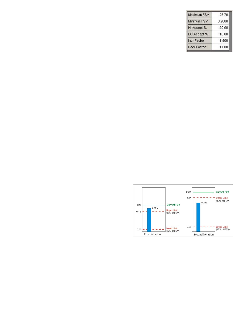
In this example we have set the radio button for
Current FSV instead of Minimum or Maximum
(note 2). The starting value, in the example, is 0.20 V.
In the first iteration we see
that we have a peak of 0.19 V.
This falls outside of our band of
0.02 to 0.18 V that was
established by our upper and
lower limit percentages; i.e.,
90% of the Current FSV and
10% of the FSV.
An Example of Auto-Ranging
As a result, the Current FSV is increased by a factor of 1.5 (our Increasing Factor) and the
Current FSV becomes 0.30 V. Our limits, in volts, also changed since we are now looking
at percentages of 0.30 volts instead of the same percentages of 0.20 volts.
In the second iteration of our example, we see a 0.22 volt peak. This value is within our
established limits so the Current FSV does not change.
Note 1: If the Capture Mode is the Input Channel (Trigger Mode), the Auto Range process waits for a
trigger.
Note 2: A Start FSV of Minimum or Maximum can selected instead of Current FSV, as in our example.
Minimum FSV is the default.