Considerations regarding double hammer rejection, Considerations regarding double, Hammer rejection – Measurement Computing eZ-PostView rev.2.0 User Manual
Page 101
eZ-Analyst
969795
Edit Menu 4-23
Edit Menu > Configuration >
Block Rejection Tab:
Hammer Rejection Panel
This panel is used to define the acceptable range for a hammer signal. Any signal outside of
the defined range is detected as a double hammer. The acceptable range will appear as a
rectangle whose boundaries are defined by high and low limits for the blocksize, and by high
and low limits for scale. Respectively, these are x- and y- axis limits.
X-axis Limits (% of blocksize): Used to set a Low point and a High point along the x-axis,
for which the hammer impact must occur to be acceptable. An example setting is 5% to 15%
(of blocksize).
Y-axis Limits (% of F(ull) S(cale): Used to set a Low point and a High point along the y-
axis, for which the hammer impact must occur to be acceptable. An example is –5.000 to
+ 5.000 (% of Full Scale).
Considerations Regarding Double Hammer Rejection
There are three major interrelated components to consider when setting up a double-hammer
rejection condition. These are:
•
Trigger Mode and Delay
•
Force Window
•
Double Hammer Region
A trigger is used to ensure time synchronous measurements across all the active channels.
As indicated in the
section of this document (beginning on page 4-6), a pre-
trigger indicates that data captured before a trigger event [the amount of which is specified
by the delay] will be prefixed to the data following the trigger event. Also, a trigger delay
[in reference to the Start Trigger Condition] indicates that a specified amount of data after
the start trigger [the amount of which is specified by the delay] will be skipped (ignored)
before a block of data is captured.
Double hammer reject is only meaningful with the pre-trigger specified
. Double
hammer rejection protects the measurement from a bad hammering.
It is desirable to set the pre-trigger to fall within the hammer region, since it is a common
practice to set the trigger channel to an impact channel.
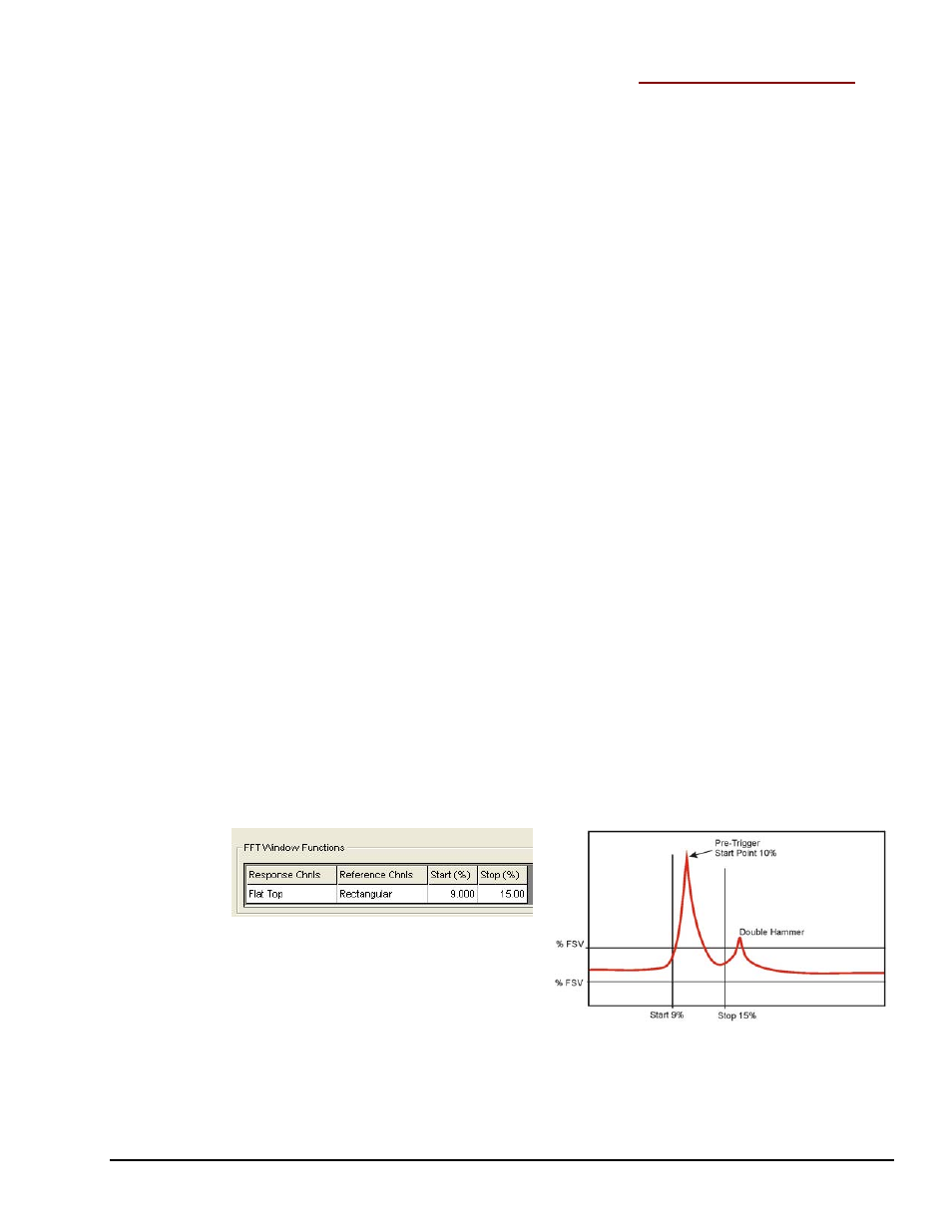
Example
In this example, a test engineer is looking for a trigger event that occurs somewhere after
10% of the data block, but before 15% of the block. Therefore:
(1) Pre-Trigger is set for 10% Delay, using the
(on the Analyzer Tab).
(2) A Rectangular Force Window is selected and set for a Start point of 9% and a Stop
point of 15%. This is done in the FFT Setup Tab’s
4-27 contains additional information.
Selecting a Rectangular Force
Window and Setting Points
for 9% and 15%
Selected and set in the FFT Setup Tab.
A Double Hammer Event
When impact testing we want to make sure that a double hammer does not occur. Through
trial and error we may start by setting the Double Hammer range at 12% and 14%, or 11%
and 13% of the block. Typically this range is fine tuned using sample acquisitions prior to
starting a real test.